
Understanding and Applying the Compressive Stress Formula for Columns and Pillars
Compressive stress is a fundamental concept in mechanical engineering, particularly crucial when analyzing the behavior of columns and pillars under load. It describes the stress state within a material subjected to a force that tends to compress or shorten it. This article provides a comprehensive guide to understanding, calculating, and applying the compressive stress formula, focusing on its relevance to structural analysis and design. We will explore the basic formula, its limitations, and its application in various real-world scenarios.
Defining Compressive Stress
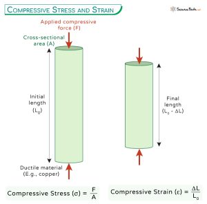
Compressive stress (often denoted as σc) is defined as the force applied perpendicularly to a surface, divided by the area over which that force is distributed. Mathematically, it is expressed as:
σc = F/A
Where: σc represents the compressive stress (typically measured in Pascals (Pa) or pounds per square inch (psi)).
F represents the compressive force applied (typically measured in Newtons (N) or pounds (lb)).
A represents the cross-sectional area over which the force is distributed (typically measured in square meters (m2) or square inches (in2)).
It's important to note the sign convention. Compressive stress is generally considerednegativewhile tensile stress (stress due to pulling) is consideredpositive. This distinction is crucial when combining different stress components in more complex analyses.
How does compressive stress differ from tensile stress?
Tensile stress is the stress experienced by an object that is being pulled apart, while compressive stress is the stress experienced by an object that is being compressed. Both are normal stresses, acting perpendicular to the surface, but in opposite directions. The same formula (σ = F/A) applies, but the sign convention differentiates between the two. Thinking of a rope being pulled (tensile) versus a brick supporting a wall (compressive) clarifies the difference.
What are the units of compressive stress?
The SI unit for compressive stress (and all stress) is the Pascal (Pa), which is equivalent to N/m². In the Imperial system, stress is commonly measured in pounds per square inch (psi) or kilopounds per square inch (ksi). It is important to maintain consistent units throughout any calculation.
Is compressive stress a scalar or vector quantity?
Stress, in general, is not a simple scalar or vector quantity. It's more accurately described by a tensor, which considers the stress acting in different directions at a point. However, when dealing with simple axial compression (as discussed in this article), we often treat compressive stress as a scalar for ease of calculation.
Applying the Compressive Stress Formula
Let's consider some practical examples of how to apply the compressive stress formula.
Example 1: A Concrete Column
A cylindrical concrete column with a diameter of 0.3 meters supports a load of 500 k N. Calculate the compressive stress in the column.
Solution
1.Calculate the cross-sectional area (A):
A = πr2 = π(d/2)2 = π(0.3 m / 2)2 = π(0.15 m)2 ≈
0.0707 m2
2.Calculate the compressive stress (σc):
σc = F/A = 500,000 N / 0.0707 m2 ≈ 7,072,136 Pa (or
7.07 MPa)
Therefore, the compressive stress in the concrete column is approximately 7.07 MPa.
Example 2: A Steel Pillar
A square steel pillar with sides of 10 cm supports a machine weighing 20,000 kg. Calculate the compressive stress in the pillar.
Solution
1.Calculate the force (F): The force is the weight of the machine, which can be calculated as F = mg, where m is the mass and g is the acceleration due to gravity (approximately
9.81 m/s2).
F = (20,000 kg)(9.81 m/s2) = 196,200 N
2.Calculate the cross-sectional area (A):
A = (0.1 m)(0.1 m) =
0.01 m2
3.Calculate the compressive stress (σc):
σc = F/A = 196,200 N / 0.01 m2 = 19,620,000 Pa (or
19.62 MPa)
Therefore, the compressive stress in the steel pillar is approximately 19.62 MPa.
Limitations and Considerations
While the compressive stress formula (σc = F/A) is simple and useful, it's important to understand its limitations: Uniform Stress Distribution:This formula assumes that the stress is uniformly distributed across the cross-sectional area. This is only true if the force is applied axially and the material is homogeneous and isotropic (having the same properties in all directions). In reality, stress concentrations can occur at points of load application or around holes, leading to higher local stresses.
Slender Columns and Buckling: The formula does not account for buckling, which is a mode of failure that occurs in slender columns subjected to compression. Buckling is a stability issue, where the column deflects laterally under load, even before the compressive stress reaches the material's yield strength. For slender columns, the Euler buckling formula or more advanced buckling analyses are necessary.
Material Properties: The formula does not directly incorporate material properties like Young's modulus (E) or Poisson's ratio (ν). These properties are important for determining the material's deformation under stress and its resistance to failure.
Combined Loading: In many real-world scenarios, columns and pillars are subjected to combined loading, including compressive, tensile, bending, and shear stresses. The simple compressive stress formula is insufficient for analyzing such complex stress states. More advanced stress analysis techniques, like Mohr's Circle or finite element analysis (FEA), are required.
Dynamic Loading: The formula is primarily applicable for static loads (loads that are applied slowly and remain constant over time). For dynamic loads (loads that vary rapidly with time), fatigue and impact effects need to be considered.
Real-World Applications
The compressive stress formula finds widespread application in various engineering fields: Structural Engineering:Design of building columns, bridge piers, and other structural elements that support compressive loads. Understanding the compressive stress is crucial to ensure the structural integrity and prevent failure due to crushing or buckling.
Geotechnical Engineering: Analysis of soil and rock under foundations, embankments, and tunnels. The compressive strength of soil and rock determines their ability to support structures without excessive deformation or failure.
Mechanical Engineering: Design of machine components subjected to compression, such as piston rods, connecting rods, and bearing supports.
Aerospace Engineering: Analysis of aircraft fuselage and wing structures under aerodynamic loads, which often include compressive components.
Pressure Vessels: While pressure vessels are often analyzed primarily for tensile stresses (hoop stress and longitudinal stress), compressive stresses can arise in specific areas, especially around supports or connections. Understanding these compressive stresses is crucial for preventing localized failures.
Advanced Considerations
For more complex scenarios, engineers need to consider advanced concepts and formulas beyond the basic compressive stress formula: Euler's Buckling Formula:For slender columns, Euler's buckling formula (Pcr = (π2EI)/(L2)) predicts the critical load (Pcr) at which buckling will occur. Here, E is Young's modulus, I is the area moment of inertia of the column's cross-section, and L is the effective length of the column.
Rankine-Gordon Formula: This formula provides a more empirical approach to buckling, considering both the compressive strength of the material and the slenderness ratio of the column. It's useful for columns that are neither very short nor very slender.
Finite Element Analysis (FEA): FEA is a powerful numerical technique that can be used to analyze complex stress distributions in columns and pillars, especially when dealing with irregular geometries, complex loading conditions, or non-homogeneous materials.
How do you calculate hoop stress in thin-walled cylinders?
Hoop stress (σh) in a thin-walled cylinder is calculated using the formula σh = (Pr)/t, where P is the internal pressure, r is the radius of the cylinder, and t is the wall thickness. This formula assumes that the stress is uniformly distributed across the wall thickness and that the cylinder's wall is "thin" (typically, r/t > 10). Although this istensilestress, understanding how loads are distributed is applicable in understanding compressive stresses in supports for those same cylinders.
What is the difference between true stress and engineering stress?
Engineering stress is calculated using the original cross-sectional area of the material, while true stress is calculated using theinstantaneouscross-sectional area, which changes during deformation. True stress provides a more accurate representation of the stress experienced by the material at a given instant, especially at high strains. Engineering stress is simpler to calculate and is often sufficient for small deformations.
When should principal stress formulas be applied in design?
Principal stress formulas are applied when dealing with complex stress states, where stresses act in multiple directions. They help determine the maximum and minimum normal stresses (principal stresses) and the maximum shear stress at a point. These values are crucial for assessing the risk of yielding or fracture under combined loading conditions. For example, when a column is under axial compression and also experiences bending, you must consider the principal stresses to ensure structural integrity.
Conclusion
The compressive stress formula is a cornerstone of structural and mechanical engineering. By understanding the formula, its limitations, and its applications, engineers can design safe and reliable structures and machines that can withstand compressive loads. While the simple formula (σc = F/A) provides a good starting point, it is crucial to consider more advanced concepts and techniques, such as buckling analysis and finite element analysis, when dealing with complex scenarios. Ultimately, a thorough understanding of compressive stress is essential for ensuring the structural integrity and longevity of engineered systems.