
Compressive Stress Formula for Structural Applications
Compressive stress is a fundamental concept in mechanical engineering and materials science, describing the stress state when a material is subjected to a force that tends to decrease its volume. This article delves into the compressive stress formula, its derivation, applications in structural engineering, and crucial considerations for accurate analysis and design. Understanding compressive stress is vital for ensuring the safety and reliability of structures and components in various engineering applications.
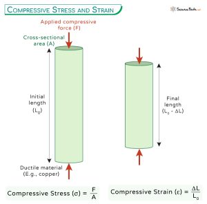
Compressive stress occurs when a force pushes or compresses a material, causing it to shorten along the direction of the force. Unlike tensile stress, which pulls or stretches a material, compressive stress squeezes it. This type of stress is critical in understanding the behavior of columns, beams, pressure vessels, and other structural elements subjected to loads that tend to compress them.
Defining Compressive Stress and the Formula
Compressive stress (σc) is defined as the force (F) applied perpendicular to a surface divided by the area (A) over which the force is distributed. Mathematically, this is expressed as:
σc = F / A
Where: σc represents the compressive stress, typically measured in Pascals (Pa) or pounds per square inch (psi).
F represents the compressive force acting on the material, measured in Newtons (N) or pounds (lb).
A represents the cross-sectional area of the material perpendicular to the direction of the applied force, measured in square meters (m2) or square inches (in2).
It's important to note that compressive stress is typically considered negative, distinguishing it from tensile stress, which is considered positive. This sign convention helps to differentiate between forces that compress and forces that stretch the material. However, for magnitude calculations, the absolute value of the force and area are used.
Derivation of the Formula
The compressive stress formula is derived directly from the definition of stress as force per unit area. Imagine a solid rectangular block subjected to a compressive force acting uniformly across one of its faces. The force is distributed equally across every infinitesimal area element on that face. Summing up the force contributions from all these infinitesimal areas gives the total force F, and dividing by the total area A yields the average compressive stress. This assumes that the stress is uniformly distributed across the cross-section. In reality, stress concentrations can occur at points of geometric discontinuity or load application, which can affect the distribution and magnitude of the actual compressive stress.
Applications of the Compressive Stress Formula
The compressive stress formula finds extensive applications across various engineering disciplines, including: Structural Engineering:Calculating the compressive stress in columns, pillars, and foundations is crucial for ensuring structural stability. Understanding the compressive strength of materials used in these structures helps prevent buckling and collapse under load. For example, in designing a bridge support, engineers must accurately determine the compressive stress in the concrete piers to prevent failure.
Pressure Vessels: While pressure vessels are primarily designed to withstand internal pressure (leading to tensile stress), external pressure induces compressive stress. The compressive stress must be accounted for in the design to prevent implosion or buckling of the vessel walls.
Beams: Although beams are primarily subjected to bending stresses, the compressive stress on the concave (top) side of a bending beam must be considered, especially for short, stocky beams. Euler's column formula, related to buckling, can become relevant if the compressive region is long and slender. The stress distribution varies linearly through the beam's cross-section, with maximum compressive stress occurring at the extreme fiber.
Rotating Machinery: Components in rotating machinery, such as shafts and bearings, experience both compressive and tensile stresses due to centrifugal forces and applied loads. Accurate analysis of these stresses is essential to prevent fatigue failure and ensure the safe operation of the machinery.
Thermal Stress: Temperature changes can induce thermal stresses in materials due to expansion or contraction. If a material is constrained from expanding or contracting freely, compressive stresses can develop if the temperature increases, and tensile stresses can develop if the temperature decreases. The magnitude of thermal stress depends on the coefficient of thermal expansion, the temperature change, and the material's Young's modulus.
Worked Examples
Example 1: Concrete Column under Axial Load
A circular concrete column with a diameter of 0.5 meters is subjected to an axial compressive load of 5 MN (5,000,000 N). Calculate the compressive stress in the column.
Step 1: Calculate the cross-sectional area.
A = πr2 = π(0.25 m)2 ≈
0.1963 m2
Step 2: Apply the compressive stress formula.
σc = F / A = 5,000,000 N / 0.1963 m2 ≈
25.47 x 10⁶ Pa =
25.47 MPa
Therefore, the compressive stress in the concrete column is approximately 25.47 MPa.
Example 2: Steel Rod Under Compression
A steel rod with a square cross-section of 20 mm x 20 mm is subjected to a compressive force of 80 k N. Determine the compressive stress in the rod.
Step 1: Calculate the cross-sectional area.
A = (20 mm) x (20 mm) = 400 mm2 = 400 x 10-6 m2 = 0.0004 m2
Step 2: Apply the compressive stress formula.
σc = F / A = 80,000 N / 0.0004 m2 = 200 x 106 Pa = 200 MPa
Therefore, the compressive stress in the steel rod is 200 MPa.
Factors Affecting Compressive Stress
Several factors can influence the compressive stress in a material or structure: Material Properties:The material's compressive strength, Young's modulus, and Poisson's ratio significantly affect its response to compressive forces. Materials with high compressive strength can withstand greater compressive stresses before failure.
Geometry: The shape and dimensions of the component play a crucial role. Slender columns are more susceptible to buckling under compression, while thicker components can withstand higher compressive loads.
Load Application: The way the load is applied also matters. Uniformly distributed loads generally result in more predictable stress patterns compared to concentrated loads, which can cause stress concentrations.
Boundary Conditions: How the component is supported or constrained affects the stress distribution. Fixed supports provide greater resistance to deformation and can influence the magnitude and location of maximum compressive stress.
Temperature: As mentioned earlier, temperature changes can induce thermal stresses. Uneven temperature distributions can create complex stress patterns that include compressive stress in certain regions.
Common Pitfalls and Misconceptions
Assuming Uniform Stress Distribution: The compressive stress formula assumes a uniform distribution of stress across the cross-sectional area. In reality, stress concentrations can occur at corners, holes, or other geometric discontinuities, leading to higher stresses in those areas. Finite element analysis (FEA) can be used to more accurately determine the stress distribution in such cases.
Ignoring Buckling: For slender columns, buckling is a critical failure mode that must be considered in addition to compressive stress. Euler's column formula is used to determine the critical buckling load, which is the load at which the column will buckle rather than crush.
Confusing Stress and Strength: Compressive stress is the stresswithina material due to an applied load, while compressive strength is a material property representing its ability towithstandcompressive stress before failure (crushing or yielding). Exceeding the compressive strength leads to permanent deformation or fracture.
Applying the Formula to Non-Axial Loads: The formula σc = F/A is strictly applicable to axial compressive loads, where the force is applied perpendicular to the cross-sectional area. For loads applied at an angle, or for combined loading scenarios (e.g., bending and compression), more complex stress analysis techniques are required.
How do you calculate hoop stress in thin-walled cylinders?
Hoop stress (σh) in a thin-walled cylinder is calculated using the formula σh = (P r) / t, where P is the internal pressure, r is the radius of the cylinder, and t is the wall thickness. This formula assumes that the cylinder is thin-walled (i.e., the wall thickness is significantly smaller than the radius).
What is the difference between true stress and engineering stress?
Engineering stress is calculated by dividing the applied force by theoriginalcross-sectional area of the material. True stress, on the other hand, is calculated by dividing the applied force by theinstantaneouscross-sectional area of the material during deformation. True stress is more accurate than engineering stress, especially at large strains, because it accounts for the reduction in area that occurs during deformation.
When should principal stress formulas be applied in design?
Principal stress formulas should be applied when a material is subjected to complex loading conditions, such as combined tension, compression, and shear. Principal stresses represent the maximum and minimum normal stresses at a point, and their orientations are known as the principal planes. These values are crucial for predicting failure under multi-axial stress states, especially when using failure theories like the maximum shear stress theory or the distortion energy theory (Von Mises criterion). They are vital in designs where the stress state is complex and not simply uniaxial tension or compression.
Conclusion
The compressive stress formula, σc = F/A, provides a fundamental tool for analyzing and designing structures and components subjected to compressive loads. By understanding the principles behind this formula, its applications, and the factors that can influence compressive stress, engineers can ensure the safety and reliability of their designs. Remember to consider potential stress concentrations, buckling, and the material's compressive strength to avoid catastrophic failures. Accurate application of the compressive stress formula, coupled with sound engineering judgment, is crucial for creating robust and durable structures.