
Essential Formulas for Stress in Engineering Mechanics
Stress is a fundamental concept in engineering mechanics, representing the internal forces that molecules within a continuous material exert on each other. It's crucial for understanding how structures and components behave under load, predicting failure, and designing safe and reliable engineering systems. This article provides a comprehensive overview of essential stress formulas, covering various loading conditions and geometries, along with practical examples to aid understanding.
Normal Stress (Axial Stress)
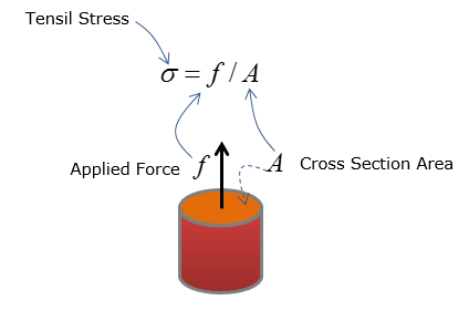
Normal stress, often denoted by σ (sigma), is a measure of the force acting perpendicular to a surface. It is a result of tensile or compressive loading.
Formula
σ = F/A
Where: σ = Normal stress (typically in Pascals (Pa) or pounds per square inch (psi))
F = Force acting normal to the surface (in Newtons (N) or pounds (lb))
A = Cross-sectional area over which the force acts (in square meters (m²) or square inches (in²))
Example
Consider a steel rod with a diameter of 20 mm subjected to a tensile force of 50 k N. The cross-sectional area is A = πr² = π(0.01 m)² ≈
3.14 x 10⁻⁴ m².
Therefore, the normal stress is: σ = (50,000 N) / (3.14 x 10⁻⁴ m²) ≈
159.2 MPa.
Important Considerations
A positive stress value indicates tensile stress (pulling), while a negative value indicates compressive stress (pushing).
This formula assumes that the force is uniformly distributed over the cross-sectional area. Stress concentrations, which occur at points of geometric discontinuity (e.g., holes, sharp corners), can significantly alter the stress distribution and must be considered in design.
How does stress relate to strain?
Stress and strain are directly related through the material's constitutive law. For linearly elastic materials, this relationship is defined by Hooke's Law:
σ = Eε
Where:
E = Young's Modulus (a material property representing stiffness) ε = Strain (a dimensionless measure of deformation, defined as the change in length divided by the original length)
Hooke's Law is only valid within the elastic limit of the material. Beyond this limit, the material will experience permanent deformation.
What is the difference between true stress and engineering stress?
Engineering stress, calculated using the original cross-sectional area, is simpler to compute but less accurate for large deformations. True stress, calculated using the instantaneous cross-sectional area, provides a more accurate representation of the stress experienced by the material as it deforms. The difference becomes significant when materials undergo substantial necking or area reduction before failure.
Engineering Stress: σe = F/A0 (A0 is the original area)
True Stress: σt = F/Ai (Ai is the instantaneous area)
Shear Stress
Shear stress, denoted by τ (tau), arises when a force acts parallel to a surface, causing it to deform by sliding or shearing.
Formula
τ = V/A
Where: τ = Shear stress (typically in Pascals (Pa) or pounds per square inch (psi))
V = Shear force acting parallel to the surface (in Newtons (N) or pounds (lb))
A = Area over which the shear force acts (in square meters (m²) or square inches (in²))
Example
Consider a bolt connecting two plates, subjected to a shear force of 10 k N. If the bolt has a diameter of 10 mm, the shear area is A = πr² = π(0.005 m)² ≈
7.85 x 10⁻⁵ m².
The shear stress in the bolt is: τ = (10,000 N) / (7.85 x 10⁻⁵ m²) ≈
127.4 MPa.
Common Applications
Bolted and riveted connections
Cutting and punching operations
Torsion in shafts
Bending Stress in Beams
Beams subjected to transverse loads experience both bending moments and shear forces. Bending stress, a type of normal stress, varies linearly across the beam's cross-section, with maximum stress occurring at the outermost fibers.
Formula
σ = My/I
Where: σ = Bending stress (typically in Pascals (Pa) or pounds per square inch (psi))
M = Bending moment at the section (in Newton-meters (N·m) or pound-inches (lb·in))
y = Distance from the neutral axis to the point where stress is being calculated (in meters (m) or inches (in))
I = Area moment of inertia of the cross-section about the neutral axis (in meters to the fourth power (m⁴) or inches to the fourth power (in⁴))
Maximum Bending Stress
The maximum bending stress occurs at the point farthest from the neutral axis (y = c):
σmax = Mc/I
Example
A rectangular beam with a width of 50 mm and a height of 100 mm is subjected to a bending moment of 5 k N·m. The area moment of inertia is I = (1/12)bh³ = (1/12)(0.05 m)(0.1 m)³ ≈
4.17 x 10⁻⁶ m⁴. The distance from the neutral axis to the outermost fiber is c = h/2 =
0.05 m.
The maximum bending stress is: σmax = (5000 N·m)(0.05 m) / (4.17 x 10⁻⁶ m⁴) ≈
59.95 MPa.
Key Considerations
The area moment of inertia (I) is a geometric property that reflects the beam's resistance to bending. Different cross-sectional shapes have different I values.
The neutral axis is the axis within the beam that experiences no stress during bending.
This formula assumes that the beam is made of a linearly elastic material and that bending is small (small deflection theory).
How do you calculate the area moment of inertia for different cross-sections?
The area moment of inertia depends on the shape of the cross-section. Here are some common examples: Rectangle: I = (1/12)bh³, where b is the width and h is the height. Circle: I = (π/64)d⁴, where d is the diameter. Hollow Circle:I = (π/64)(D⁴ - d⁴), where D is the outer diameter and d is the inner diameter.
How does shear force affect bending stress calculations?
While the bending stress formula focuses on the bending moment, shear force also contributes to the overall stress state in a beam. Shear stress is generally maximum at the neutral axis and decreases towards the outer fibers. For short, deep beams, shear stress can be significant and must be considered. However, for long, slender beams, the bending stress is usually dominant.
Torsional Shear Stress in Shafts
Torsion occurs when a twisting moment (torque) is applied to a shaft. This results in shear stress within the shaft.
Formula
τ = Tρ/J
Where: τ = Torsional shear stress (typically in Pascals (Pa) or pounds per square inch (psi))
T = Applied torque (in Newton-meters (N·m) or pound-inches (lb·in)) ρ = Radial distance from the center of the shaft to the point where stress is being calculated (in meters (m) or inches (in))
J = Polar moment of inertia of the shaft's cross-section (in meters to the fourth power (m⁴) or inches to the fourth power (in⁴))
Maximum Shear Stress
The maximum shear stress occurs at the outer surface of the shaft (ρ = r):
τmax = Tr/J
Polar Moment of Inertia (J)
Solid Circular Shaft: J = (π/2)r⁴ = (π/32)d⁴
Hollow Circular Shaft: J = (π/2)(ro⁴ - ri⁴) = (π/32)(do⁴ - di⁴)
Where:
ro and do are the outer radius and diameter respectively, and ri and di are the inner radius and diameter respectively.
Example
A solid circular shaft with a diameter of 50 mm is subjected to a torque of 1 k N·m. The polar moment of inertia is J = (π/32)(0.05 m)⁴ ≈
6.14 x 10⁻⁷ m⁴.
The maximum shear stress is: τmax = (1000 N·m)(0.025 m) / (6.14 x 10⁻⁷ m⁴) ≈
40.7 MPa.
Hoop Stress in Thin-Walled Cylinders
Thin-walled cylinders, such as pressure vessels, experience circumferential stress (hoop stress) and longitudinal stress when subjected to internal pressure.
Formula for Hoop Stress
σh = (pr)/t
Where: σh = Hoop stress (typically in Pascals (Pa) or pounds per square inch (psi))
p = Internal pressure (typically in Pascals (Pa) or pounds per square inch (psi))
r = Inner radius of the cylinder (in meters (m) or inches (in))
t = Wall thickness of the cylinder (in meters (m) or inches (in))
Formula for Longitudinal Stress
σl = (pr)/(2t)
Example
A thin-walled cylindrical pressure vessel has an inner radius of 1 m and a wall thickness of 10 mm. It is subjected to an internal pressure of 2 MPa.
The hoop stress is: σh = (2 MPa)(1 m) / (0.01 m) = 200 MPa.
The longitudinal stress is: σl = (2 MPa)(1 m) / (2 0.01 m) = 100 MPa.
Thin-Walled Assumption
This formula is accurate when the cylinder's wall thickness is significantly smaller than its radius (typically, r/t > 10).
How do you calculate hoop stress in thin-walled spheres?
For thin-walled spheres, the stress is uniform and equal in all directions. The formula is:
σ = (pr)/(2t)
This is half the hoop stress in a cylinder under the same conditions.
Combined Stress and Principal Stresses
In many real-world scenarios, components are subjected to multiple types of stresses simultaneously (e.g., bending and torsion). The combined stress state can be analyzed using stress transformation equations to determine the principal stresses and maximum shear stress.
Principal Stresses
The principal stresses (σ₁ and σ₂) are the maximum and minimum normal stresses acting on an element at a specific orientation where the shear stress is zero.
σ1,2 = (σx + σy)/2 ± √[((σx - σy)/2)² + τxy²]
Where: σx and σy are the normal stresses in the x and y directions, respectively. τxy is the shear stress in the xy plane.
Maximum Shear Stress
τmax = √[((σx - σy)/2)² + τxy²] = (σ₁ - σ₂)/2
Example
An element in a stressed body is subjected to the following stresses: σx = 100 MPa, σy = 50 MPa, and τxy = 25 MPa.
The principal stresses are:
σ1,2 = (100 + 50)/2 ± √[((100 - 50)/2)² + 25²] = 75 ± √(625 + 625) = 75 ± 35.36 MPa
σ₁ ≈ 110.36 MPa
σ₂ ≈ 39.64 MPa
The maximum shear stress is: τmax = (110.36 -
39.64)/2 ≈
35.36 MPa
When should principal stress formulas be applied in design?
Principal stress formulas are crucial for determining the maximum stresses within a component subjected to complex loading conditions. These maximum stress values are then used in failure criteria (e.g., Von Mises yield criterion, maximum shear stress criterion) to assess the component's safety and predict its potential for yielding or fracture. They are essential when combined loading is present or when analyzing stress concentrations.
Thermal Stress
Thermal stress arises when a material is subjected to a temperature change and is constrained from expanding or contracting freely.
Formula
σ = αEΔT
Where: σ = Thermal stress (typically in Pascals (Pa) or pounds per square inch (psi)) α = Coefficient of thermal expansion (a material property) (typically in 1/°C or 1/°F)
E = Young's modulus (a material property) (typically in Pascals (Pa) or pounds per square inch (psi)) ΔT = Change in temperature (in °C or °F)
Example
A steel bar is heated from 20°C to 100°C and is constrained from expanding. The coefficient of thermal expansion for steel is 12 x 10⁻⁶ /°C, and Young's modulus is 200 GPa.
The thermal stress is: σ = (12 x 10⁻⁶ /°C)(200 x 10⁹ Pa)(100°C - 20°C) = 192 MPa (compressive).
This article provides a foundation for understanding essential stress formulas in engineering mechanics. Remember that these formulas are simplified representations of complex phenomena and may not be applicable in all situations. Always consider the assumptions and limitations of each formula and consult with experienced engineers for critical applications. Furthermore, software tools utilizing Finite Element Analysis (FEA) are invaluable for analyzing complex geometries and loading scenarios, providing accurate stress distributions where analytical solutions are insufficient. Always remember to define the formula before using it and properly report units with final answers.