
Understanding the Torsional Stress Formula and Its Use in Shaft Design
Torsional stress is a critical concept in mechanical engineering, particularly when designing shafts and other components subjected to twisting forces. Understanding the torsional stress formula and its proper application is essential for ensuring the structural integrity and reliability of rotating machinery. This article will delve into the derivation of the formula, explore its use in shaft design, and address common challenges and misconceptions.
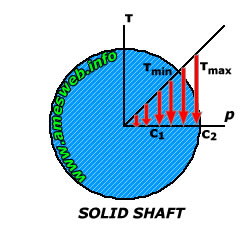
Torsional stress arises when a torque (or twisting moment) is applied to an object, causing shear stress within the material. Imagine twisting a cylindrical rod; the outer layers experience the greatest shear stress, while the center experiences minimal stress. The ability to accurately calculate this stress is paramount in designing shafts that can withstand the applied torque without failure.
Derivation of the Torsional Stress Formula
The torsional stress formula relates the applied torque, the geometry of the shaft (specifically its polar moment of inertia), and the resulting shear stress. The derivation relies on several key assumptions: The material is homogeneous and isotropic: This means the material properties are uniform throughout and are the same in all directions. The shaft is circular: While the formula can be adapted for non-circular cross-sections, the derivation is simplest for circular shafts. Plane sections remain plane: This assumption implies that cross-sections of the shaft remain flat and perpendicular to the axis of rotation after the torque is applied. Elastic behavior: The material behaves elastically, meaning it returns to its original shape after the torque is removed. This implies stresses remain below the yield strength.
Starting with the relationship between shear strain (γ) and the angle of twist (θ) over a length (L) of the shaft with radius (r):
γ = rθ/L
Shear stress (τ) is related to shear strain through the shear modulus (G):
τ = Gγ
Substituting the first equation into the second, we get:
τ = Grθ/L
Now, consider a small area element (d A) on the cross-section of the shaft at a distance (r) from the center. The force acting on this area is d F = τd A. The torque contributed by this force is d T = r d F = rτd A. Substituting for τ, we have:
d T = r (Grθ/L) d A = (Gθ/L) r² d A
To find the total torque (T) acting on the shaft, we integrate over the entire cross-sectional area:
T = ∫ d T = (Gθ/L) ∫ r² d A
The integral ∫ r² d A is the polar moment of inertia (J) of the cross-section. Therefore:
T = (Gθ/L) J
Finally, rearranging this equation to solve for θ/L:
θ/L = T/GJ
Substituting this back into the equation for shear stress (τ = Grθ/L), we arrive at thetorsional stress formula:
τ = Tr/J
Where: τ is the shear stress at a distance r from the center of the shaft.
T is the applied torque.
r is the radial distance from the center of the shaft to the point where the stress is being calculated.
J is the polar moment of inertia of the shaft's cross-section. For a solid circular shaft, J = πd⁴/32, where d is the diameter. For a hollow circular shaft with outer diameter D and inner diameter d, J = π(D⁴ - d⁴)/32.
Using the Torsional Stress Formula in Shaft Design
The torsional stress formula is fundamental in designing shafts for various applications, from automotive axles to power transmission systems. The primary goal is to ensure the shear stress in the shaft remains below the allowable shear stress for the material, preventing failure.
Design Steps
1.Determine the Applied Torque (T): This is often dictated by the power transmitted by the shaft and its rotational speed (ω). The relationship is: P = Tω, where P is power in Watts and ω is in radians per second. Therefore, T = P/ω. Convert units appropriately.
2.Choose a Material: Select a material with appropriate strength, stiffness (shear modulus G), and fatigue properties for the application. Common choices include steel alloys.
3.Determine the Allowable Shear Stress (τallowable): This is usually a fraction of the material's yield strength in shear or its ultimate tensile strength, divided by a safety factor (SF). τallowable = (Yield Strength in Shear) / SF, or τallowable = (Ultimate Tensile Strength / 2) / SF. The safety factor accounts for uncertainties in loading, material properties, and manufacturing tolerances. A common safety factor ranges from 2 to
4.
4.Calculate the Required Polar Moment of Inertia (J): Rearrange the torsional stress formula to solve for J: J = Tr/τallowable. Note that 'r' is themaximumradius of the shaft.
5.Determine the Shaft Diameter: Based on the calculated J and the shaft's geometry (solid or hollow), determine the required diameter(s). For a solid shaft: d = (32J/π)1/4. For a hollow shaft, iterate through inner and outer diameters to achieve the required J.
6.Check for Angle of Twist: In some applications, the angle of twist is a critical design parameter. Use the formula θ = TL/GJ to calculate the expected angle of twist. Ensure this value is within acceptable limits.
7.Consider Stress Concentrations: Sharp corners, keyways, and other geometric discontinuities can significantly increase stress concentrations. Use appropriate stress concentration factors (obtained from experimental data or finite element analysis) to adjust the calculated stress levels.
Example 1: Designing a Solid Shaft
A solid steel shaft is required to transmit 50 k W of power at a rotational speed of 200 RPM. The allowable shear stress for the steel is 80 MPa. Determine the required diameter of the shaft.
Solution
1.Calculate the Torque:
ω = 200 RPM = (200 2π) / 60 rad/s ≈ 20.94 rad/s
T = P/ω = (50,000 W) / (20.94 rad/s) ≈
2387.3 Nm
2.Determine Allowable Shear Stress: τallowable = 80 MPa = 80 x 106 N/m²
3.Calculate the Required Polar Moment of Inertia: J = Tr/τallowable. We can rewrite this as J/r = T/τallowable. But J/r = (πd⁴/32) / (d/2) = πd³/16. Thus, πd³/16 = T/τallowable
πd³/16 = (2387.3 N⋅m) / (80 x 106 N/m²)
d³ = (16 2387.3) / (π 80 x 106) m³ ≈
1.517 x 10⁻⁴ m³
d = (1.517 x 10⁻⁴)1/3 m ≈
0.0533 m =
53.3 mm
Therefore, the required diameter of the solid shaft is approximately 53.3 mm. You would likely select a commercially available size slightly larger than this.
Example 2: Designing a Hollow Shaft
A hollow steel shaft with an outer diameter of 100 mm is required to transmit 100 k W of power at 300 RPM. The allowable shear stress is 70 MPa. Determine the required inner diameter of the shaft.
Solution
1.Calculate the Torque:
ω = 300 RPM = (300 2π) / 60 rad/s ≈ 31.42 rad/s
T = P/ω = (100,000 W) / (31.42 rad/s) ≈
3183.1 Nm
2.Determine Allowable Shear Stress: τallowable = 70 MPa = 70 x 106 N/m²
3.Calculate the Required Polar Moment of Inertia: J = Tr/τallowable. Here, r is theouterradius = D/2 = 50 mm =
0.05 m.
J = (3183.1 N⋅m
0.05 m) / (70 x 106 N/m²) ≈
2.274 x 10⁻⁶ m⁴
4.Determine the Inner Diameter:
J = π(D⁴ - d⁴)/32
2.274 x 10-6 = π(0.1⁴ - d⁴)/32
d⁴ = 0.1⁴ - (32
2.274 x 10⁻⁶) / π ≈
6.695 x 10⁻⁵ m⁴
d = (6.695 x 10⁻⁵)1/4 m ≈
0.0508 m =
50.8 mm
Therefore, the required inner diameter of the hollow shaft is approximately 50.8 mm.
Common Pitfalls and Misconceptions
Ignoring Stress Concentrations: Stress concentrations can significantly increase the actual stress in a shaft, leading to premature failure. Always account for stress concentrations, especially at keyways, holes, or sharp corners. Assuming Constant Torque: The torque applied to a shaft may vary with time, especially in reciprocating machinery. Use the maximum torque value in the design calculations. Also consider fatigue loading due to fluctuating torques. Using the Wrong Polar Moment of Inertia: Ensure you use the correct formula for J based on the shaft's geometry (solid or hollow). Using the wrong J value will lead to incorrect stress calculations. Exceeding the Elastic Limit: The torsional stress formula is only valid when the material behaves elastically. If the shear stress exceeds the material's yield strength in shear, the shaft will experience permanent deformation. Neglecting Combined Loading:Shafts are often subjected to combined loading, including torsion, bending, and axial loads. Analyze the combined stresses to ensure the shaft can withstand the overall loading conditions. Use failure theories like the Von Mises criterion to analyze combined stresses.
How do you calculate hoop stress in thin-walled cylinders?
Hoop stress (also known as circumferential stress) in a thin-walled cylinder subjected to internal pressure (p) is calculated using the formula: σhoop = pr/t, where r is the radius of the cylinder and t is the wall thickness.
What is the difference between true stress and engineering stress?
Engineering stress is calculated by dividing the applied force by the original cross-sectional area of the material. True stress, on the other hand, is calculated by dividing the applied force by theinstantaneouscross-sectional area of the material during deformation. True stress is a more accurate measure of the stress experienced by the material at a given point in time, especially during large deformations.
When should principal stress formulas be applied in design?
Principal stress formulas are applied when a material is subjected to combined stresses (e.g., normal stress and shear stress). Principal stresses represent the maximum and minimum normal stresses at a point, acting on planes where the shear stress is zero. They are crucial for predicting failure in materials under complex loading conditions, particularly when used in conjunction with failure theories.
Conclusion
The torsional stress formula is a powerful tool for designing shafts and other components subjected to torsional loads. By understanding its derivation, assumptions, and limitations, engineers can accurately predict the stress levels in shafts and ensure their structural integrity. Proper consideration of stress concentrations, combined loading, and material properties is crucial for creating reliable and safe designs. This article has provided a comprehensive overview of the torsional stress formula and its practical application in shaft design, serving as a valuable resource for engineering students, practicing engineers, and researchers.