
In the realm of mechanical engineering and materials science, understanding stress is paramount for ensuring the safety and reliability of structures and machines. Normal stress, a fundamental concept, is the force acting perpendicular to a surface, and its accurate calculation is crucial for predicting material behavior under load. This article delves into the normal stress formula, its applications, and the complexities of combined stress analysis, offering a comprehensive guide for students, engineers, and researchers.
Understanding Normal Stress
Normal stress, often denoted by the Greek letter sigma (σ), is defined as the force acting perpendicular to a unit area. It's a measure of the intensity of the force distributed over that area. Mathematically, the normal stress formula is expressed as:
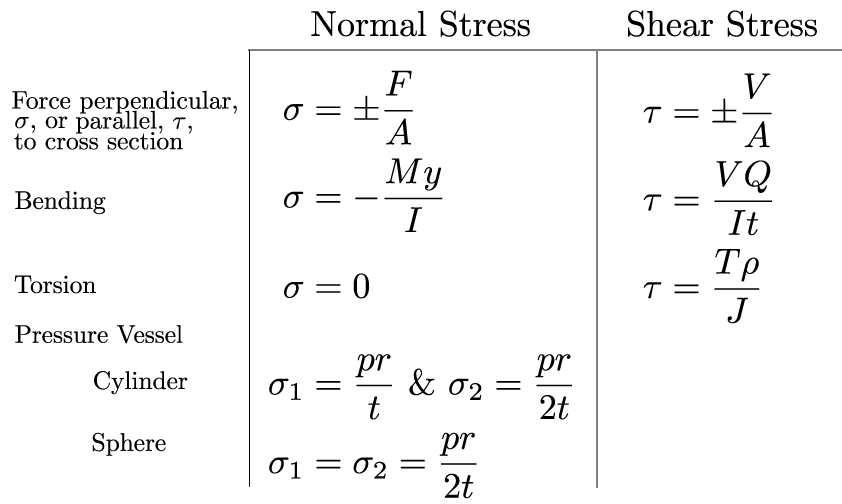
σ = F/A
where: σ represents the normal stress (typically measured in Pascals (Pa) or pounds per square inch (psi))
F represents the normal force (the force acting perpendicularly to the area, measured in Newtons (N) or pounds (lb))
A represents the cross-sectional area over which the force is applied (measured in square meters (m²) or square inches (in²))
It is important to distinguish between tensile and compressive normal stresses. Tensile stress occurs when the force pulls on the area, causing it to elongate. Compressive stress occurs when the force pushes on the area, causing it to shorten. By convention, tensile stresses are usually considered positive, while compressive stresses are negative.
The Importance of Sign Convention
Consistently adhering to a sign convention is critical in stress analysis. A positive sign generally indicates tensile stress, while a negative sign indicates compressive stress. This convention allows engineers to clearly differentiate between forces that are pulling a material apart (tension) and those that are squeezing it together (compression). Failing to maintain a consistent sign convention can lead to significant errors in subsequent calculations and ultimately, flawed designs.
Application: Axial Loading
A classic example of normal stress is axial loading, where a force is applied along the longitudinal axis of a member. Consider a steel rod subjected to a tensile force of 10,000 N. If the rod has a circular cross-section with a diameter of 10 mm (0.01 m), the normal stress can be calculated as follows:
- Calculate the cross-sectional area: A = πr² = π(0.005 m)² ≈
7.854 x 10⁻⁵ m²
- Apply the normal stress formula: σ = F/A = 10,000 N / (7.854 x 10⁻⁵ m²) ≈
127.3 MPa
This result indicates that the steel rod is experiencing a tensile stress of approximately 127.3 MPa. Comparing this value to the material's yield strength is crucial in determining whether the rod will deform permanently or fail.
Shear Stress vs. Normal Stress
While normal stress acts perpendicular to a surface, shear stress (often denoted by the Greek letter tau, τ) acts parallel to the surface. Shear stress arises from forces that cause one part of a material to slide relative to another. The shear stress formula is:
τ = V/A
where: τ represents the shear stress
V represents the shear force (the force acting parallel to the area)
A represents the area over which the shear force is applied
Consider a bolt connecting two plates. If a force is applied parallel to the plates, the bolt will experience shear stress. Understanding both normal and shear stress is critical for a complete stress analysis.
Combined Stress Analysis
In many real-world scenarios, components are subjected to multiple types of stresses simultaneously. Combined stress analysis involves determining the overall stress state at a point within a material when it is subjected to both normal and shear stresses. This often requires the use of stress transformation equations and Mohr's circle.
Stress Transformation
Stress transformation equations allow us to determine the normal and shear stresses on a plane at any arbitrary angle to the original coordinate system. These equations are derived from equilibrium considerations and trigonometric relationships. The transformed normal stress (σₓ') and shear stress (τₓ'y') on a plane inclined at an angle θ with respect to the x-axis are given by:
σₓ' = (σₓ + σᵧ)/2 + (σₓ - σᵧ)/2 cos(2θ) + τₓᵧ sin(2θ)
τₓ'y' = - (σₓ - σᵧ)/2 sin(2θ) + τₓᵧ cos(2θ)
where: σₓ and σᵧ are the normal stresses in the x and y directions, respectively τₓᵧ is the shear stress in the xy plane θ is the angle between the x-axis and the normal to the plane
Principal Stresses and Maximum Shear Stress
A key aspect of combined stress analysis is determining the principal stresses and the maximum shear stress. Principal stresses are the maximum and minimum normal stresses at a point, and they occur on planes where the shear stress is zero. The principal stresses (σ₁) and (σ₂) can be calculated as:
σ₁,₂ = (σₓ + σᵧ)/2 ± √[((σₓ - σᵧ)/2)² + τₓᵧ²]
The maximum shear stress (τmax) is given by:
τmax = √[((σₓ - σᵧ)/2)² + τₓᵧ²] = (σ₁ - σ₂)/2
These values are crucial for determining the safety factor of a component and predicting its failure mode.
Mohr's Circle
Mohr's circle is a graphical representation of the stress transformation equations. It provides a visual tool for determining the principal stresses, maximum shear stress, and the stresses on any plane at a point. Constructing Mohr's circle involves plotting the normal and shear stresses on a coordinate system and drawing a circle centered at ((σₓ + σᵧ)/2, 0) with a radius equal to τmax. The points on the circle represent the normal and shear stresses on different planes.
Example: Combined Axial and Torsional Loading
Consider a shaft subjected to both an axial tensile force and a torque. This is a common scenario in rotating machinery. The axial force will induce a normal stress, while the torque will induce a shear stress. To analyze the combined stress state at a point on the surface of the shaft, we would:
- Calculate the normal stress due to the axial force using σ = F/A.
- Calculate the shear stress due to the torque using the torsion formula τ = Tρ/J, where T is the torque, ρ is the radius of the shaft, and J is the polar moment of inertia.
- Use the stress transformation equations or Mohr's circle to determine the principal stresses and maximum shear stress at the point.
- Compare the calculated stresses to the material's yield strength or ultimate tensile strength to assess the safety of the shaft.
Real-World Applications
Normal stress and combined stress analysis are essential in a wide range of engineering applications.
Pressure Vessels
Pressure vessels, such as tanks and pipelines, are subjected to internal pressure that creates both hoop stress (circumferential stress) and longitudinal stress (axial stress). Accurate calculation of these stresses is critical for ensuring the structural integrity of the vessel. The hoop stress (σh) in a thin-walled cylindrical pressure vessel is given by:
σh = (pr)/t
where:
p is the internal pressure
r is the radius of the cylinder
t is the wall thickness
The longitudinal stress (σl) is given by:
σl = (pr)/(2t)
Beams
Beams are structural members designed to resist bending loads. Bending induces both normal stresses (tensile on one side and compressive on the other) and shear stresses within the beam. The bending stress (σ) at a distance y from the neutral axis is given by:
σ = (My)/I
where:
M is the bending moment
y is the distance from the neutral axis
I is the area moment of inertia
Rotating Machinery
Components in rotating machinery, such as shafts, gears, and turbine blades, are subjected to complex stress states due to centrifugal forces, torsional loads, and bending moments. Combined stress analysis is crucial for designing these components to withstand the high stresses and prevent fatigue failure.
Structural Analysis
In structural engineering, normal stress calculations are fundamental for analyzing the stresses in buildings, bridges, and other structures. Finite element analysis (FEA) software is often used to perform complex stress analyses, but a solid understanding of the underlying principles of normal stress and combined stress is essential for interpreting the results and ensuring the accuracy of the simulations.
Thermal Stress
Temperature changes can induce thermal stresses in materials due to thermal expansion or contraction. If a material is constrained from expanding or contracting freely, thermal stresses will develop. The thermal stress (σth) is given by:
σth = EαΔT
where:
E is the modulus of elasticity α is the coefficient of thermal expansion ΔT is the change in temperature
Common Pitfalls and Misconceptions
Confusing Stress and Force
It's crucial to remember that stress is not the same as force. Stress is the force per unit area, representing the intensity of the force.
Ignoring Sign Conventions
Failing to adhere to a consistent sign convention can lead to significant errors in stress analysis. Always clearly define and consistently apply the sign convention being used.
Assuming Uniform Stress Distribution
The normal stress formula σ = F/A assumes a uniform stress distribution across the area. However, in many cases, the stress distribution is non-uniform, particularly near stress concentrations such as holes or sharp corners.
Overlooking Shear Stress
In many situations, both normal and shear stresses are present. Neglecting shear stress when it is significant can lead to an incomplete and inaccurate stress analysis.
Practical Examples
Example 1: Tensile Test
A tensile test is performed on a cylindrical steel specimen with a diameter of 12.5 mm. The specimen is subjected to a tensile force of 50,000 N. Calculate the normal stress in the specimen.
- Calculate the cross-sectional area: A = πr² = π(0.00625 m)² ≈
1.227 x 10⁻⁴ m²
- Apply the normal stress formula: σ = F/A = 50,000 N / (1.227 x 10⁻⁴ m²) ≈
407.4 MPa
The normal stress in the steel specimen is approximately 407.4 MPa.
Example 2: Beam Bending
A rectangular beam with a width of 50 mm and a height of 100 mm is subjected to a bending moment of 5 k N·m. Calculate the maximum bending stress in the beam.
- Calculate the area moment of inertia: I = (bh³)/12 = (0.05 m (0.1 m)³)/12 ≈
4.167 x 10⁻⁶ m⁴
- Determine the maximum distance from the neutral axis: ymax = h/2 =
0.1 m / 2 =
0.05 m
- Apply the bending stress formula: σmax = (Mymax)/I = (5000 N·m
0.05 m) / (4.167 x 10⁻⁶ m⁴) ≈ 60 MPa
The maximum bending stress in the beam is approximately 60 MPa.
Conclusion
Understanding the normal stress formula and its application in combined stress analysis is fundamental for mechanical engineers and materials scientists. By mastering these concepts and considering real-world applications, engineers can design safer, more reliable structures and machines. Accurate stress analysis, along with careful consideration of material properties and loading conditions, is crucial for preventing failures and ensuring the long-term performance of engineering systems.
How do you calculate hoop stress in thin-walled cylinders?
Hoop stress (σh) in thin-walled cylinders is calculated using the formula σh = (p\*r)/t, where p is the internal pressure, r is the radius of the cylinder, and t is the wall thickness.
What is the difference between true stress and engineering stress?
Engineering stress is calculated using the original cross-sectional area of the material, while true stress is calculated using the instantaneous cross-sectional area during deformation. True stress provides a more accurate representation of the stress state at large strains.
When should principal stress formulas be applied in design?
Principal stress formulas are applied when a component is subjected to combined stresses (normal and shear) to determine the maximum and minimum normal stresses experienced by the material. These values are crucial for predicting yielding or fracture under complex loading conditions.