
Torsional Stress Formula in Power Transmission Systems
Torsional stress is a critical consideration in the design and analysis of power transmission systems. It arises when a twisting force, or torque, is applied to a structural member, causing shear stress within the material. Understanding the torsional stress formula and its applications is essential for engineers to ensure the safe and efficient operation of rotating machinery, shafts, axles, and other components subject to torsion. This article provides a comprehensive overview of torsional stress, its calculation, and its significance in various engineering applications.
Understanding Torsional Stress
Torsional stress is a type of shear stress induced in a material due to the application of a torque. This torque causes the material to twist about its longitudinal axis. The magnitude of torsional stress depends on the applied torque, the geometry of the component (specifically, its cross-sectional shape and size), and the material properties. Unlike tensile or compressive stress, which act normal to the surface, torsional stress acts parallel to the surface, causing shear deformation.
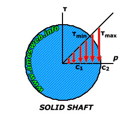
Consider a solid circular shaft subjected to a torque T. The torsional stress is highest at the outer surface of the shaft and decreases linearly towards the center, where it is zero. This distribution is crucial for understanding failure mechanisms and optimizing designs.
The Torsional Stress Formula
The fundamental torsional stress formula for a solid or hollow circular shaft is given by:
τ = (T r) / J
Where: τ (tau) is the torsional shear stress at a radial distancerfrom the center of the shaft.
T is the applied torque.
r is the radial distance from the center of the shaft to the point where the stress is being calculated.
J is the polar moment of inertia of the shaft's cross-section.
The polar moment of inertia (J) represents the resistance of a cross-section to torsional deformation. For a solid circular shaft with radius R, J is calculated as:
J = (π R4) / 2
For a hollow circular shaft with outer radius Rand inner radiusr, J is calculated as:
J = (π (R4 - r4)) / 2
The maximum torsional shear stress (τmax) occurs at the outer surface of the shaft (r = R):
τmax = (T R) / J
Substituting the value of J for a solid circular shaft, we get:
τmax = (2 T) / (π R3)
Key Considerations
Assumptions: This formula assumes that the material is homogeneous, isotropic, and linearly elastic. It also assumes that the shaft is straight and has a uniform circular cross-section. Deviations from these assumptions can lead to inaccuracies in the calculated stress values. Units: It's crucial to maintain consistent units throughout the calculation. Torque is typically expressed in Newton-meters (N·m) or pound-feet (lb·ft), radius in meters (m) or inches (in), and stress in Pascals (Pa) or pounds per square inch (psi). Stress Concentration:The presence of keyways, holes, or sharp corners can lead to stress concentrations, where the actual stress significantly exceeds the calculated stress. These areas require careful analysis and potentially the use of stress concentration factors.
Applications in Power Transmission Systems
The torsional stress formula is widely used in the design and analysis of various components in power transmission systems, including: Shafts: Shafts are used to transmit power from one component to another, such as from an engine to a gearbox or from a motor to a pump. Calculating the torsional stress in shafts is crucial to ensure that they can withstand the applied torque without yielding or fracturing. Axles: Axles are used to support rotating wheels or gears. They are subjected to both torsional and bending stresses. Understanding the torsional stress component is essential for designing axles that can handle the combined loading. Drive Shafts: Drive shafts, such as those used in automobiles, transmit power from the engine to the wheels. These shafts are often subjected to high torsional stresses, especially during acceleration and braking. Gearboxes: Gearboxes use gears to change the speed and torque of a rotating shaft. The gears themselves and the shafts on which they are mounted are subjected to torsional stresses.
Example Problems
Example 1: Solid Shaft
A solid circular steel shaft with a diameter of 50 mm is subjected to a torque of 500 N·m. Calculate the maximum torsional shear stress in the shaft.
Solution
1.Calculate the radius: R = Diameter / 2 = 50 mm / 2 = 25 mm =
0.025 m
2.Calculate the polar moment of inertia: J = (π R4) / 2 = (π (0.025 m)4) / 2 ≈
6.136 x 10⁻⁸ m4
3.Calculate the maximum torsional shear stress: τmax = (T R) / J = (500 N·m
0.025 m) / (6.136 x 10⁻⁸ m4) ≈
20.37 x 10⁶ Pa =
20.37 MPa
Therefore, the maximum torsional shear stress in the shaft is approximately 20.37 MPa.
Example 2: Hollow Shaft
A hollow circular shaft has an outer diameter of 100 mm and an inner diameter of 60 mm. It is subjected to a torque of 10 k N·m. Calculate the maximum torsional shear stress in the shaft.
Solution
1.Calculate the outer and inner radii: R = 100 mm / 2 = 50 mm =
0.05 m, r = 60 mm / 2 = 30 mm =
0.03 m
2.Calculate the polar moment of inertia: J = (π (R4 - r4)) / 2 = (π ((0.05 m)4 - (0.03 m)4)) / 2 ≈
8.545 x 10⁻⁷ m4
3.Calculate the maximum torsional shear stress: τmax = (T R) / J = (10000 N·m
0.05 m) / (8.545 x 10⁻⁷ m4) ≈
585.1 x 10⁶ Pa =
585.1 MPa
Therefore, the maximum torsional shear stress in the shaft is approximately 585.1 MPa.
Design Considerations and Safety Factors
When designing power transmission systems, it is essential to consider the allowable torsional stress for the material being used. This is typically determined by dividing the material's yield strength or ultimate tensile strength by a safety factor.
Safety factors are used to account for uncertainties in material properties, loading conditions, and manufacturing processes. A higher safety factor is typically used for critical applications where failure could have catastrophic consequences.
Beyond Circular Shafts: Non-Circular Cross-Sections
While the torsional stress formula presented earlier is specifically for circular shafts, many power transmission components have non-circular cross-sections (e.g., square, rectangular, or elliptical). The analysis of torsional stress in non-circular cross-sections is more complex and often requires the use of advanced techniques such as finite element analysis (FEA).
For a rectangular shaft, the maximum shear stress occurs at the middle of the longer side and is given by:
τmax = (T) / (α b h2)
Where: bis the shorter side. his the longer side. α is a factor that depends on the ratio h/b and can be found in tables or calculated using empirical formulas. The value of α increases as the ratio h/b increases.
Common Pitfalls and Misconceptions
Ignoring Stress Concentrations: Failing to account for stress concentrations at keyways, holes, or sharp corners can lead to underestimation of the actual stress and potential failure. Applying Circular Shaft Formula to Non-Circular Sections: The torsional stress formula for circular shafts cannot be directly applied to non-circular sections. Using the circular shaft formula for a non-circular section will result in significant errors. Neglecting Combined Loading:In many applications, shafts are subjected to both torsional and bending stresses. It is crucial to consider the combined effect of these stresses when designing the shaft.
Related Stress Formulas and Concepts
It's helpful to understand how torsional stress relates to other types of stress and related concepts in mechanics of materials: Shear Stress vs. Normal Stress: Shear stress acts parallel to a surface, while normal stress acts perpendicular to a surface (tensile or compressive). Torsional stress is a specific type of shear stress. Hoop Stress: Hoop stress is the circumferential stress in a cylindrical pressure vessel. While not directly related to torsion, it's another example of stress calculation in mechanical components. Principal Stresses: Principal stresses are the maximum and minimum normal stresses at a point. In a pure torsion scenario, the principal stresses are oriented at 45 degrees to the axis of the shaft and are equal in magnitude to the maximum torsional shear stress. True Stress vs. Engineering Stress: Engineering stress is calculated based on the original cross-sectional area of the material, while true stress is calculated based on the instantaneous cross-sectional area. True stress is more accurate at higher strains.
People Also Ask
How do you calculate the angle of twist due to torsion?
The angle of twist (θ) in radians for a circular shaft subjected to a torque Tis given by:
θ = (T L) / (G J)
Where:
L is the length of the shaft.
G is the shear modulus of the material.
J is the polar moment of inertia.
This formula is crucial for designing shafts where excessive twisting could impair functionality.
What materials are best suited for applications involving high torsional stress?
Materials with high shear strength and high shear modulus are best suited for applications involving high torsional stress. Examples include high-strength steels, alloy steels, and certain composite materials. The specific material selection depends on the specific application requirements, including cost, weight, and operating environment.
How does temperature affect torsional stress?
Temperature can affect torsional stress by influencing the material properties. At elevated temperatures, the shear modulus and yield strength of materials typically decrease, which can lead to higher stress levels and increased susceptibility to failure. Thermal expansion can also induce additional stresses in constrained components. Therefore, it is important to consider the operating temperature range when designing components that are subjected to torsional stress.
Conclusion
The torsional stress formula is a fundamental tool for engineers designing and analyzing power transmission systems. By understanding the principles of torsional stress and its calculation, engineers can ensure the safe and efficient operation of rotating machinery and other components subjected to twisting forces. Remember to account for stress concentrations, material properties, and combined loading scenarios to achieve robust and reliable designs. This article provides a solid foundation for further exploration of advanced topics in stress analysis and mechanical design.