
What the Ultimate Stress Formula Reveals About Material Strength
Stress. It's a word that evokes tension, strain, and potential failure. In mechanical engineering, understanding stress is paramount to designing safe and reliable structures and components. While there isn’t a single, all-encompassing “ultimate” stress formula, the underlying principles that govern stress analysis are fundamental. By dissecting these principles, we can gain invaluable insights into material strength and its crucial role in engineering design. This article will explore the various forms of stress, the formulas used to calculate them, and how these calculations reveal critical information about a material's ability to withstand applied loads.
Understanding the Fundamentals of Stress
Stress, in its most basic definition, is the internal resistance offered by a material to an external load. It's a measure of the force acting over a cross-sectional area. This resistance is what prevents the material from deforming or failing. The fundamental stress formula is:
σ = F/A
Where: σ (sigma) represents the stress (typically measured in Pascals (Pa) or pounds per square inch (psi)).
F represents the force applied (measured in Newtons (N) or pounds (lb)).
A represents the cross-sectional area over which the force is applied (measured in square meters (m²) or square inches (in²)).
This formula provides a starting point, but the reality is often more complex. The type of stress depends on the direction of the force relative to the area. We primarily distinguish between normal stress and shear stress. Normal stress acts perpendicular to the area, while shear stress acts parallel to the area.
Normal Stress: Tension and Compression
Normal stress, also known as tensile or compressive stress, is the stress component perpendicular to the surface. When the force pulls on the area (tension), the stress is tensile and is considered positive. When the force pushes on the area (compression), the stress is compressive and is considered negative. Imagine pulling on a steel cable (tension) versus pushing down on a column (compression).
The same fundamental formula applies (σ = F/A), but the sign convention distinguishes between the two types of normal stress. It’s crucial to specify whether the stress is tensile or compressive in any calculation or analysis.
Shear Stress: Sliding Action
Shear stress, denoted by τ (tau), occurs when the force is applied parallel to the area. This type of stress tends to cause one portion of the material to slide relative to the adjacent portion. Think of cutting paper with scissors; the blades exert a shear stress on the paper.
The shear stress formula is:
τ = F/A
Where: τ (tau) represents the shear stress (typically measured in Pascals (Pa) or pounds per square inch (psi)).
F represents the shear force applied (measured in Newtons (N) or pounds (lb)).
A represents the area parallel to the force (measured in square meters (m²) or square inches (in²)).
A common example is the shear stress experienced by a bolt connecting two plates subjected to a tensile load. The bolt must resist the tendency of the plates to slide past each other.
Beyond Simple Stress: More Complex Scenarios
The simple stress formulas (σ = F/A and τ = F/A) are excellent for introductory calculations, but most real-world engineering applications involve more complex stress states. Factors such as bending, torsion, pressure, and thermal effects can all contribute to the overall stress experienced by a component.
Bending Stress: The Result of Moments
Bending stress occurs in structural elements subjected to bending moments, such as beams. The bending moment causes tension on one side of the beam and compression on the other, with a neutral axis where the stress is zero. The bending stress formula is:
σ = My/I
Where: σ (sigma) represents the bending stress.
M represents the bending moment.
y represents the distance from the neutral axis to the point where the stress is being calculated.
I represents the area moment of inertia of the cross-section.
The area moment of inertia (I) is a geometric property of the cross-section that indicates its resistance to bending. A larger area moment of inertia means a greater resistance to bending.
Torsional Stress: Twisting Forces
Torsional stress occurs in elements subjected to a twisting moment, such as shafts. The torsional stress is maximum at the outer surface of the shaft and zero at the center. The torsional stress formula is:
τ = Tr/J
Where: τ (tau) represents the torsional stress.
T represents the torque.
r represents the distance from the center of the shaft to the point where the stress is being calculated.
J represents the polar moment of inertia of the cross-section.
The polar moment of inertia (J) is a geometric property that indicates a shaft's resistance to torsion.
Hoop Stress in Thin-Walled Pressure Vessels
Thin-walled pressure vessels, such as pipes and tanks, experience hoop stress (circumferential stress) and longitudinal stress due to the internal pressure. The hoop stress is generally twice as large as the longitudinal stress. The hoop stress formula is:
σ_hoop = (Pr)/t
Where: σ_hoop represents the hoop stress.
P represents the internal pressure.
r represents the radius of the vessel.
t represents the wall thickness.
Thermal Stress: The Impact of Temperature
Thermal stress arises when a material is subjected to a temperature change and is constrained from expanding or contracting freely. The thermal stress formula is:
σ = EαΔT
Where: σ (sigma) represents the thermal stress.
E represents the modulus of elasticity of the material. α represents the coefficient of thermal expansion of the material. ΔT represents the change in temperature.
High thermal stresses can lead to material failure, especially in constrained systems.
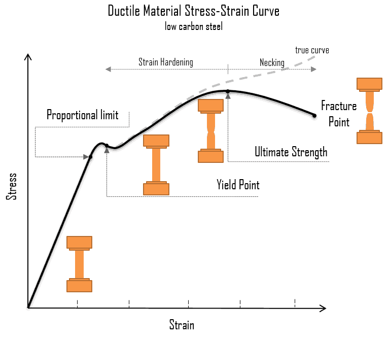
Unveiling Material Strength: Yield Strength and Ultimate Tensile Strength
Understanding stress is only half the battle. We also need to understand a material's strength – its ability to withstand stress without failing. Two key material properties are yield strength and ultimate tensile strength.
Yield Strength (σ_y): This is the stress at which a material begins to deform permanently (plastically). Below the yield strength, the material will return to its original shape after the load is removed. Ultimate Tensile Strength (σ_u): This is the maximum stress a material can withstand before it starts to neck (significantly reduce in cross-sectional area) and ultimately fracture.
These values are typically determined through tensile testing and are crucial for selecting appropriate materials for a given application.
Applying Stress Formulas: A Practical Example
Let's consider a steel rod with a diameter of 20 mm subjected to a tensile force of 50 k N. We want to calculate the tensile stress in the rod.
1.Calculate the cross-sectional area: A = πr² = π(0.01 m)² ≈
0.000314 m²
2.Calculate the tensile stress: σ = F/A = (50,000 N) / (0.000314 m²) ≈
159.2 MPa
If the yield strength of the steel is 250 MPa, the rod will not yield under this load because the calculated stress (159.2 MPa) is less than the yield strength. However, if the force were increased, eventually the tensile stress would exceed the yield strength, leading to permanent deformation.
Accounting for Safety: Factor of Safety
In real-world engineering, we always incorporate a factor of safety (FOS) to account for uncertainties in material properties, loading conditions, and manufacturing processes. The factor of safety is the ratio of the material's strength (either yield strength or ultimate tensile strength) to the allowable stress.
FOS = Material Strength / Allowable Stress
A higher factor of safety indicates a more conservative design. The appropriate FOS depends on the application, the consequences of failure, and the level of confidence in the design parameters. For example, aircraft components typically have higher factors of safety than components in less critical applications.
Common Pitfalls and Misconceptions
Confusing Stress and Strain: Stress is the internal resistance to an external force, while strain is the deformation of the material due to the applied stress. They are related by the material's modulus of elasticity (E): σ = Eε, where ε is the strain. Assuming Uniform Stress Distribution: The simple stress formulas assume a uniform stress distribution over the cross-sectional area. This is often not the case, especially near stress concentrations (e.g., holes, sharp corners). Finite element analysis (FEA) is often used to accurately determine stress distributions in complex geometries. Ignoring Stress Concentrations: Stress concentrations can significantly increase the local stress experienced by a component. Properly accounting for stress concentrations is essential for preventing premature failure. Using Engineering Stress vs. True Stress: Engineering stress is calculated using the original cross-sectional area, while true stress is calculated using the instantaneous cross-sectional area. At higher strains, the difference between engineering stress and true stress becomes significant. True stress is a more accurate representation of the stress state at the point of necking and fracture.
How do you calculate hoop stress in thin-walled cylinders?
The hoop stress in a thin-walled cylinder is calculated using the formula: σ_hoop = (Pr)/t, where P is the internal pressure, r is the radius of the cylinder, and t is the wall thickness. This formula assumes that the cylinder is thin-walled, meaning that the wall thickness is much smaller than the radius (typically t < r/10).
What is the difference between true stress and engineering stress?
Engineering stress is calculated using the original cross-sectional area of a material, while true stress is calculated using the instantaneous cross-sectional area during deformation. Engineering stress is simpler to calculate but less accurate at large deformations because it doesn't account for the reduction in area due to necking. True stress provides a more accurate representation of the stress state during plastic deformation.
When should principal stress formulas be applied in design?
Principal stresses are the maximum and minimum normal stresses at a point on a loaded body, acting on planes with zero shear stress. Principal stress formulas should be applied when designing components subjected to complex loading conditions that result in combined stresses (e.g., combined bending and torsion). The principal stresses can be used to predict the onset of yielding or fracture based on failure criteria like the maximum shear stress theory or the von Mises criterion. These criteria use the principal stresses to determine if the combined stress state exceeds the material's strength.
Conclusion
The "ultimate" stress formula is not a single equation, but rather a comprehensive understanding of the principles of stress analysis and material strength. By carefully considering the type of loading, the geometry of the component, and the material properties, engineers can accurately predict the stress distribution within a structure and ensure its safe and reliable operation. From simple tensile tests to complex finite element simulations, the underlying principles of stress and material strength remain fundamental to the practice of mechanical engineering. Mastery of these concepts is essential for creating innovative and dependable designs that meet the challenges of the modern world.