
When to Use the True Stress Formula in Engineering
In the realm of mechanical engineering and materials science, accurately determining stress is paramount for ensuring the structural integrity and performance of components and systems. While the engineering stress formula provides a convenient and often sufficient approximation, it's crucial to understand its limitations and when the true stress formula becomes necessary for precise analysis. This article delves into the true stress formula, exploring its derivation, applications, and the scenarios where its use is vital for reliable engineering designs.
The concept of stress, in its most basic form, is the force acting per unit area within a deformable body. Engineering stress, also known as nominal stress, is defined as the applied force divided by theoriginalcross-sectional area of the material. This holds true under the assumption that the change in cross-sectional area during deformation is negligible. However, as materials undergo significant plastic deformation, particularly during processes like tensile testing beyond the yield point, this assumption breaks down. The cross-sectional area changes considerably, and using the original area leads to an underestimation of the actual stress experienced by the material. This is where the true stress formula comes into play.
Defining and Deriving True Stress
True stress, also known as instantaneous stress, accounts for the instantaneous cross-sectional area of the material as it deforms. It's a more accurate representation of the stress the material isactuallyexperiencing at any given point during deformation. Mathematically, true stress (σt) is defined as:
σt = F / Ai
where:
F is the applied force.
Ai is the instantaneous cross-sectional area.
To understand the relationship between true stress and engineering stress, consider a tensile test. Engineering stress (σe) is given by:
σe = F / Ao
where Ao is the original cross-sectional area.
The relationship between true strain (εt) and engineering strain (εe) is defined as:
εt = ln(1 + εe)
Assuming constant volume during plastic deformation (a reasonable assumption for many metals), we can relate the instantaneous area to the original area:
AoLo = AiLi
Where Lo and Li are the original and instantaneous lengths, respectively. Rearranging, we get:
Ai = Ao (Lo / Li) = Ao / (Li/Lo) = Ao / (1 + εe)
Substituting this expression for Ai into the true stress equation:
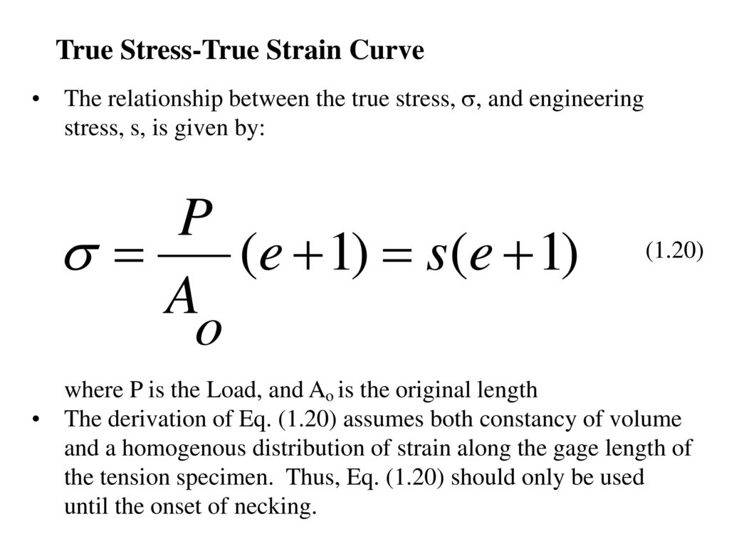
σt = F / [Ao / (1 + εe)] = (F / Ao) (1 + εe)
Therefore, the relationship between true stress and engineering stress is:σt = σe (1 + εe)
This equation highlights that true stress is always greater than engineering stress after the start of necking in a tensile test, and the difference becomes increasingly significant as the strain increases. Up to the point of necking, the difference between the two is smaller but still exists.
When to Use True Stress
The decision of whether to use true stress or engineering stress depends on the specific application and the level of accuracy required. Here are some scenarios where using the true stress formula is crucial: Large Plastic Deformations:When a material undergoes significant plastic deformation (e.g., metal forming processes like forging, rolling, and extrusion), the change in cross-sectional area is substantial. Using engineering stress would lead to inaccurate predictions of material behavior and potential failure. True stress provides a more accurate representation of the stress state within the material, leading to more reliable process design and control.
Finite Element Analysis (FEA) of Forming Processes: In FEA simulations of metal forming, accurately modeling material behavior under large plastic strains is essential. Constitutive models based on true stress and true strain are necessary for realistic predictions of stress distributions, deformation patterns, and the final shape of the formed part. Ignoring the difference between true and engineering stress can lead to significant errors in simulation results.
Fracture Mechanics: While not always directly usingtruestress, advanced fracture mechanics analyses often require stress-strain curves that accurately represent the material behaviorup to fracture. Using engineering stress-strain data in such analyses can lead to inaccurate predictions of crack growth and fracture toughness, especially for ductile materials. Converting engineering stress-strain data to true stress-strain data provides a more accurate representation of the material's resistance to fracture.
High-Strain Rate Applications: In situations involving high strain rates, such as impact loading or explosive forming, materials can exhibit significantly different behavior compared to quasi-static conditions. True stress-strain curves, often obtained from specialized high-strain-rate testing, are essential for accurately modeling material response and predicting structural integrity under these extreme conditions.
Material Characterization Beyond Yielding: When studying the fundamental mechanical behavior of materials, particularly beyond the yield point, true stress-strain curves provide valuable insights into strain hardening, necking, and other phenomena. This information is critical for developing and validating material models and for understanding the relationship between microstructure and mechanical properties.
Creep Analysis at Elevated Temperatures: While creep is a time-dependent deformation under constant stress, the true stress can be used in conjunction with creep constitutive equations to more accurately model the changing stress and strain rates as the material's cross-sectional area changes. This is particularly important over long durations.
Examples of True Stress in Engineering Applications
Let's look at some specific examples where the true stress formula is essential: Forging of an Aluminum Alloy Connecting Rod:When forging a connecting rod from an aluminum alloy, the material undergoes substantial plastic deformation to achieve the desired shape. Finite element simulations are used to optimize the forging process, predict die stresses, and ensure the final part meets dimensional tolerances. Using true stress-strain data in the FEA model is crucial for accurately predicting material flow, preventing defects like laps and folds, and optimizing die design.
Deep Drawing of a Steel Cup: In the deep drawing process, a flat sheet of steel is formed into a cup-shaped component. The material experiences significant stretching and thinning during the process. If the engineering stress-strain curve is used in simulations, it will underpredict the actual stress in the material, leading to inaccuracies in predicting thinning and potential tearing. True stress-strain data, along with accurate friction modeling, are essential for optimizing the process parameters and preventing defects.
Tensile Testing of a Ductile Metal: In a standard tensile test, the engineering stress-strain curve deviates significantly from the true stress-strain curve after the onset of necking. If you need to understand the actual behavior of the material up to the point of fracture, using the true stress-strain curve is critical.
Worked-Out Examples
Example 1: Calculating True Stress and True Strain from Engineering Stress and Strain
A cylindrical steel specimen with an initial diameter of 12.5 mm is subjected to a tensile test. At a certain point, the applied force is 45 k N, and the gauge length has increased from 50 mm to 55 mm. Calculate the engineering stress, engineering strain, true stress, and true strain at this point.
Engineering Stress:
Ao = π(d/2)2 = π(12.5 mm / 2)2 =
122.72 mm2
σe = F / Ao = 45000 N / 122.72 mm2 =
366.7 MPa
Engineering Strain:
εe = (Li - Lo) / Lo = (55 mm - 50 mm) / 50 mm = 0.1
True Strain:
εt = ln(1 + εe) = ln(1 + 0.1) =
0.0953
True Stress:
σt = σe (1 + εe) = 366.7 MPa (1 +
0.1) =
403.4 MPa
Example 2: Effect of Necking on Stress Calculations
Consider a copper wire with an original diameter of 2 mm pulled in tension. At the onset of necking, the engineering stress is measured to be 250 MPa and the engineering strain is 0.2. However, at the point of fracture, the diameter at the neck has reduced to 1 mm, and the force is observed to be 628 N. Calculate the true stress at the point of fracture.
Original Area:
Ao = π(2 mm / 2)2 = π mm2
Fracture Area:
Af = π(1 mm / 2)2 = π/4 mm2
True Stress at Fracture:
σtf = F / Af = 628 N / (π/4 mm2) = 800 MPa (approximately)
Notice how the true stress at fracture (800 MPa) is considerably higher than the engineering stress at the onset of necking (250 MPa), demonstrating the significant difference when accounting for area reduction.
Pitfalls and Misconceptions
A common misconception is that true stress is always necessary foranystress calculation. For small deformations and stresses below the yield strength of the material, the difference between true stress and engineering stress is often negligible, and using the simpler engineering stress formula is perfectly adequate. However, it's crucial to be aware of the limitations and to apply engineering judgment to determine when the more accurate true stress formula is required. Also, remember that constant volume assumption is an approximation. For materials with significant porosity or volume changes during deformation, more complex models may be needed.
Another pitfall is incorrectly applying the true stress and true strain equations without understanding the assumptions behind them. Ensure that the assumptions of constant volume and uniform deformation (up to the point of necking) are reasonably valid for the specific application.
People Also Ask:
How do you calculate hoop stress in thin-walled cylinders?
Hoop stress (σh) in a thin-walled cylinder subjected to internal pressure (p) is calculated using the following formula: σh = (p r) / t, where r is the radius of the cylinder and t is the wall thickness. This formula assumes that the wall thickness is significantly smaller than the radius (typically t < r/10). This calculates the engineering stress. If the cylinder undergoes substantial plastic deformation, especially at elevated temperatures, thetruehoop stress should be considered in conjunction with material creep models.
What is the difference between true stress and engineering stress?
Engineering stress is calculated using the original cross-sectional area of the material, while true stress is calculated using the instantaneous cross-sectional area. Engineering stress is a convenient approximation for small deformations, while true stress provides a more accurate representation of the stress state under large plastic deformations.
When should principal stress formulas be applied in design?
Principal stress formulas are applied when analyzing components subjected to multiaxial stress states. They help determine the maximum and minimum normal stresses (principal stresses) and the maximum shear stress at a point, regardless of the orientation of the coordinate system. These values are crucial for predicting yielding, fracture, and fatigue failure under complex loading conditions, as they allow engineers to compare the multiaxial stress state to material strength criteria (e.g., Von Mises criterion).
Conclusion
Understanding the difference between true stress and engineering stress, and knowing when to apply the true stress formula, is essential for accurate stress analysis and reliable engineering design. While engineering stress provides a convenient approximation for many applications, true stress becomes crucial when dealing with large plastic deformations, metal forming processes, fracture mechanics, and high-strain-rate phenomena. By mastering the concepts and applications discussed in this article, engineers can ensure the structural integrity and performance of components and systems in a wide range of engineering applications.