
Normal stress, a fundamental concept in mechanics of materials, describes the intensity of a force acting perpendicular to a surface. Understanding and calculating normal stress is crucial for engineers involved in structural design, material selection, and failure analysis. This article delves into the normal stress formula for pressure on planes, exploring its derivation, applications, and limitations, providing a comprehensive resource for students and practicing engineers.
Defining Normal Stress and its Significance
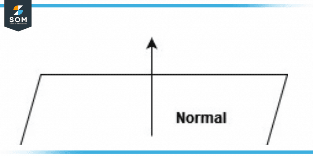
Normal stress (often denoted by the Greek letter sigma, σ) quantifies the force acting perpendicularly (or "normally") to a given area. It is expressed as the force (F) divided by the area (A) over which it acts:
σ = F/A
The units of normal stress are typically Pascals (Pa) or pounds per square inch (psi). A positive normal stress indicates tensile stress (pulling force), while a negative normal stress signifies compressive stress (pushing force). The concept of normal stress is central to analyzing the behavior of materials under load. It forms the basis for more complex stress analyses, including those involving shear stress, bending stress, and combined loading. Properly understanding and calculating normal stress is critical for ensuring the structural integrity and safety of engineering designs. Without it, structures could fail prematurely due to exceeding their material's strength limits.
Deriving the Normal Stress Formula for Pressure on Planes
When a plane surface is subjected to pressure, the normal stress is directly related to the pressure intensity. Consider a small area elementd Aon the plane surface. If the pressure acting on this area element is P, then the normal forced Facting on the area element is given by:
d F = P d A
Integrating over the entire area Aof the plane, we get the total normal force:
F = ∫ P d A
If the pressure Pis uniform over the entire area A, the integral simplifies to:
F = P A
Now, we can find the normal stress by dividing the total normal force by the area:
σ = F/A = (P A) / A
Therefore, for a uniform pressure on a plane:
σ = P
This seemingly simple equation is incredibly powerful. It shows that the normal stress induced by a uniform pressure on a plane is equal to the pressure itself. It is crucial to remember this relationship holds true when the pressure is uniformly distributed over the area. In situations with non-uniform pressure distributions, more complex integration methods are required to determine the equivalent normal stress.
Applications of the Normal Stress Formula
The normal stress formula for pressure on planes has wide-ranging applications across various engineering disciplines.
Pressure Vessels
Pressure vessels, such as tanks and pipelines, are designed to contain fluids or gases under pressure. The internal pressure exerts normal stresses on the vessel walls. The hoop stress (circumferential stress) and longitudinal stress are both types of normal stresses that must be carefully calculated to prevent vessel failure. For thin-walled pressure vessels, the hoop stress (σh) is calculated as:
σh = (P r) / t
where Pis the internal pressure,ris the radius of the vessel, andtis the wall thickness. Similarly, the longitudinal stress (σl) is:
σl = (P r) / (2 t)
These equations demonstrate how the normal stress formula is adapted for specific geometries and loading conditions. The design of pressure vessels relies heavily on accurately predicting these normal stresses to ensure the vessel can safely withstand the applied pressure.
Structural Analysis of Beams
While bending stress is dominant in beams, normal stress components arise from axial loads or reactions. If a beam is subjected to a direct axial force Fin addition to bending, the normal stress due to the axial force can be calculated as σ = F/A, where Ais the cross-sectional area of the beam. The total normal stress at any point on the beam's cross-section is then the sum of the bending stress and the axial stress. Analyzing the combined effect of these stresses is critical for determining the overall safety and performance of the beam.
Hydraulic Systems
Hydraulic systems utilize pressurized fluids to transmit power. The pressure in the hydraulic fluid creates normal stresses on the components of the system, such as pistons and cylinders. Understanding these stresses is vital for designing hydraulic components that can withstand the operating pressures without yielding or fracturing. The same formula, σ = P, can be used to determine the normal stress acting on the piston face due to the hydraulic pressure. This allows engineers to select appropriate materials and dimensions for the piston and cylinder to ensure reliable operation.
Soil Mechanics
In soil mechanics, effective stress is a key concept that involves normal stress. The total stress (σ) acting on a soil element is the sum of the effective stress (σ') and the pore water pressure (u):
σ = σ' + u
The effective stress is the stress carried by the soil solids and is responsible for the soil's strength and deformation behavior. While seemingly related to normal stress due to pressure, the key is the 'effective' component, which considers the pore water's influence. When analyzing the stability of slopes or the bearing capacity of foundations, understanding and calculating the effective stress, which is a form of normal stress, is crucial.
People Also Ask Section:
How do you calculate hoop stress in thin-walled cylinders?
Hoop stress, also known as circumferential stress, in a thin-walled cylinder subjected to internal pressure is calculated using the formula σh = (P r) / t, where P is the internal pressure, r is the radius of the cylinder, and t is the wall thickness. This formula assumes that the wall thickness is much smaller than the radius (typically, t < r/10). For thick-walled cylinders, more complex formulas are required to account for the varying stress distribution through the wall thickness.
What is the difference between true stress and engineering stress?
Engineering stress is calculated by dividing the applied force by theoriginalcross-sectional area of the material. True stress, on the other hand, is calculated by dividing the applied force by theinstantaneouscross-sectional area of the material during deformation. Engineering stress is simpler to calculate, but true stress provides a more accurate representation of the stress state, especially at large deformations. As a material stretches or necks under tensile load, the cross-sectional area decreases. True stress accounts for this change, while engineering stress does not.
When should principal stress formulas be applied in design?
Principal stress formulas should be applied in design when the material is subjected to complex loading conditions that result in multiple stress components acting simultaneously. Principal stresses represent the maximum and minimum normal stresses at a point, acting on planes where the shear stress is zero. These stresses are crucial for predicting failure, especially in brittle materials. Determining the principal stresses and comparing them to the material's strength allows engineers to assess the safety of the design under combined loading scenarios, such as combined bending and torsion. Mohr's circle is a graphical tool often used to determine principal stresses.
Worked Examples
Example 1: Pressure Vessel
A cylindrical pressure vessel with an internal diameter of 1 meter and a wall thickness of 10 mm is subjected to an internal pressure of 2 MPa. Calculate the hoop stress and longitudinal stress in the vessel wall.
Solution:
Internal radius, r = 0.5 m = 500 mm
Wall thickness, t = 10 mm
Internal pressure, P = 2 MPa
Hoop stress, σh = (P r) / t = (2 MPa 500 mm) / 10 mm = 100 MPa
Longitudinal stress, σl = (P r) / (2 t) = (2 MPa 500 mm) / (2 10 mm) = 50 MPa
Therefore, the hoop stress in the vessel wall is 100 MPa, and the longitudinal stress is 50 MPa.
Example 2: Hydraulic Cylinder
A hydraulic cylinder has a piston with a diameter of 50 mm. The hydraulic pressure is 15 MPa. Calculate the normal stress acting on the piston face.
Solution:
Piston diameter, d = 50 mm
Hydraulic pressure, P = 15 MPa
Since the pressure is uniformly distributed over the piston face, the normal stress is equal to the pressure:
σ = P = 15 MPa
Therefore, the normal stress acting on the piston face is 15 MPa.
Common Pitfalls and Misconceptions
One common mistake is neglecting the units. Always ensure that the force and area are expressed in consistent units (e.g., Newtons and square meters, or pounds-force and square inches). A mix-up in units can lead to significant errors in the calculated stress value.
Another misconception is applying the simple σ = P formula to non-uniform pressure distributions. In cases where the pressure varies across the area, it's necessary to integrate the pressure over the area to determine the total force and then calculate the average normal stress or use more advanced stress analysis techniques to determine the local stress values.
Finally, it's essential to remember that the normal stress formula only applies to forces acting perpendicular to the surface. Forces acting parallel to the surface (shear forces) induce shear stresses, which require different calculation methods.
Advanced Considerations
For more complex geometries or loading conditions, finite element analysis (FEA) software can be used to determine the normal stress distribution. FEA allows engineers to model intricate structures and simulate their response to various loads, providing a detailed picture of the stress distribution within the material.
Furthermore, when dealing with dynamic loading conditions (i.e., loads that vary with time), fatigue analysis becomes critical. Repeated application of normal stresses can lead to fatigue failure, even if the stress levels are below the material's yield strength. Fatigue analysis involves considering the stress range (the difference between the maximum and minimum stress values) and the number of load cycles to predict the fatigue life of the component.
Conclusion
The normal stress formula for pressure on planes, σ = P, is a fundamental tool in engineering. While seemingly simple, its correct application is essential for ensuring the safety and reliability of various engineering designs. Understanding the assumptions, limitations, and applications of this formula, along with recognizing potential pitfalls, empowers engineers to make informed decisions and develop robust and durable structures. From pressure vessels to hydraulic systems, the principles of normal stress analysis are indispensable for creating safe and efficient engineering solutions.