
Compressive stress is a fundamental concept in mechanical engineering, crucial for understanding the behavior of materials under load and for ensuring the safe and efficient design of structures and components. It arises when a force is applied to an object, causing it to be squeezed or compressed. Understanding the compressive stress formula and its applications in load testing is essential for engineers involved in design, analysis, and quality control. This article provides a comprehensive overview of compressive stress, its calculation, and its significance in various engineering applications.
Understanding Compressive Stress
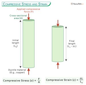
Compressive stress (often denoted by σc) is defined as the force per unit area acting perpendicular to a surface that tends to compress or shorten the material. It is a normal stress, meaning that the force acts perpendicular to the area. Unlike tensile stress, which pulls the material apart, compressive stress pushes it together.
Mathematically, compressive stress is represented as:
σc = F/A
Where: σc is the compressive stress (typically measured in Pascals (Pa) or pounds per square inch (psi)).
F is the compressive force applied (typically measured in Newtons (N) or pounds (lb)).
A is the cross-sectional area perpendicular to the direction of the applied force (typically measured in square meters (m²) or square inches (in²)).
It's important to note the sign convention. While stress is fundamentally a tensor quantity, in many simplified scenarios we treat it as a scalar. Conventionally, compressive stress is often assigned a negative sign, to distinguish it from tensile stress which is typically positive. However, the sign convention can vary depending on the context and the software being used for analysis.
Calculating Compressive Stress in Load Testing
Load testing is a critical procedure in engineering to assess the structural integrity and performance of materials and components under various loading conditions. The compressive stress formula plays a vital role in analyzing the results of these tests. By applying a known compressive force to a specimen and measuring its cross-sectional area, engineers can determine the compressive stress induced in the material.
The process generally involves the following steps:
1.Specimen Preparation: The material to be tested is machined or formed into a specific shape and dimensions, ensuring accurate measurement of the cross-sectional area. Standardized test specimens are often used to facilitate comparisons between different materials.
2.Load Application: A compressive load is applied to the specimen using a testing machine, such as a universal testing machine (UTM). The applied force is carefully controlled and monitored throughout the test.
3.Data Acquisition: Measurements of the applied force and the resulting deformation (strain) are recorded using sensors and data acquisition systems. Strain gauges are commonly used to measure the deformation of the specimen under load.
4.Stress Calculation: Using the measured force and cross-sectional area, the compressive stress is calculated using the formula σc = F/A. The stress is usually plotted against the strain to generate a stress-strain curve, which provides valuable information about the material's mechanical properties.
Applications of Compressive Stress Formula
The compressive stress formula and the understanding of compressive stress are fundamental to many areas of engineering. Here are a few key applications: Structural Engineering: In designing buildings, bridges, and other structures, engineers must consider the compressive stresses induced in columns, walls, and foundations due to the weight of the structure and external loads like wind and snow. Understanding the compressive strength of concrete, steel, and other construction materials is vital to ensuring structural stability and preventing collapse. Geotechnical Engineering: Compressive stress is crucial in soil mechanics and rock mechanics. It is used to analyze the stability of slopes, the bearing capacity of soils under foundations, and the behavior of rocks under pressure in underground excavations. The compressive strength of soil and rock is a key parameter in geotechnical design. Mechanical Engineering: The design of machine components like shafts, gears, and bearings involves analyzing compressive stresses. Consider a piston rod in an engine. The piston rod experiences significant compressive stress during the combustion stroke, where the force from the expanding gases pushes on the piston. Engineers use the compressive stress formula to calculate the stress in the rod and select a material with sufficient strength to withstand the load without buckling or failing. Material Science: Studying the compressive behavior of materials provides insights into their fundamental properties and helps in developing new materials with improved strength and durability. Compressive testing is used to characterize the compressive strength, elastic modulus, and other mechanical properties of various materials, including metals, polymers, ceramics, and composites. Aerospace Engineering:Aircraft components, such as fuselage panels and wing spars, are subjected to compressive stresses during flight. The compressive stress formula helps in determining the required material thickness and structural design to withstand these loads and prevent structural failure.
Examples of Compressive Stress Calculations
Let's consider a couple of practical examples to illustrate the application of the compressive stress formula.
Example 1: Concrete Column
A cylindrical concrete column with a diameter of 300 mm is subjected to a compressive load of 1.5 MN (Mega Newtons). Calculate the compressive stress in the column.
1.Calculate the cross-sectional area:
A = πr² = π(d/2)² = π(0.3 m / 2)² = π(0.15 m)² ≈
0.0707 m²
2.Calculate the compressive stress:
σc = F/A = -1.5 MN /
0.0707 m² = -1.5 × 10⁶ N /
0.0707 m² ≈ -21.2 MPa (Mega Pascals)
Therefore, the compressive stress in the concrete column is approximately -21.2 MPa.
Example 2: Steel Rod
A rectangular steel rod with dimensions 20 mm x 40 mm is subjected to a compressive force of 200 k N (kilo Newtons). Calculate the compressive stress in the rod.
1.Calculate the cross-sectional area:
A = width x height = 0.02 m x
0.04 m =
0.0008 m²
2.Calculate the compressive stress:
σc = F/A = -200 k N / 0.0008 m² = -200 × 10³ N /
0.0008 m² = -250 MPa
Therefore, the compressive stress in the steel rod is -250 MPa.
Factors Affecting Compressive Stress
Several factors can influence the compressive stress experienced by a material or component: Applied Load: The magnitude of the compressive force directly affects the compressive stress. A higher force results in a higher stress. Cross-sectional Area: The area over which the force is distributed is inversely proportional to the compressive stress. A smaller area results in a higher stress. Material Properties: The material's Young's modulus (elasticity) and compressive strength play a significant role in determining its behavior under compression. Materials with higher Young's modulus will exhibit less deformation under the same stress. Geometry: The shape and dimensions of the component can affect the stress distribution. For example, stress concentrations can occur at sharp corners or holes, leading to higher local stresses. Loading Conditions: The way in which the load is applied (e.g., axial, eccentric, or bending) can influence the stress distribution. Eccentric loading can induce bending stresses in addition to compressive stresses. Temperature: Temperature changes can induce thermal stresses in materials, which can add to or subtract from the compressive stress caused by external loads. Thermal expansion and contraction can lead to significant stresses, especially in constrained structures.
Common Pitfalls and Misconceptions
Confusing Stress with Force: Stress is the force per unit area, while force is simply a push or pull. It is crucial to differentiate between the two concepts. A large force applied over a small area results in high stress, while the same force applied over a large area results in lower stress. Ignoring Stress Concentrations: Stress concentrations can significantly increase the local stress levels at certain points in a component. These concentrations can lead to premature failure, even if the average stress is below the material's yield strength. It's crucial to consider stress concentrations in design and analysis, especially at geometric discontinuities like holes, corners, and notches. Assuming Uniform Stress Distribution: The compressive stress formula assumes a uniform distribution of stress across the cross-sectional area. This assumption is valid for simple geometries and axial loading. However, in more complex scenarios, the stress distribution may be non-uniform, requiring more advanced analysis techniques like finite element analysis (FEA). Neglecting Buckling: Slender columns subjected to compressive loads can buckle, which is a form of instability that leads to sudden and catastrophic failure. The compressive stress formula alone cannot predict buckling. Buckling analysis requires considering the column's length, cross-sectional shape, and end conditions. Euler's formula is often used to estimate the critical buckling load.
Advanced Considerations
While the basic compressive stress formula (σc = F/A) is useful for simple scenarios, more complex situations may require advanced analysis techniques. These include: Finite Element Analysis (FEA): FEA is a powerful numerical method for analyzing stress distributions in complex geometries and under various loading conditions. FEA software divides the component into a mesh of small elements and solves the governing equations of elasticity to determine the stress and strain at each element. Photoelasticity: Photoelasticity is an experimental technique that uses polarized light to visualize stress distributions in transparent materials. This technique can be used to validate FEA results and to gain insights into the stress behavior of complex components. Strain Gauges: Strain gauges are small sensors that are attached to the surface of a component to measure its strain under load. Strain measurements can be used to calculate the stress using the material's stress-strain relationship. Principal Stresses: In complex loading scenarios, a component may experience stresses in multiple directions. Principal stresses are the maximum and minimum normal stresses at a point, and they are oriented on planes where the shear stress is zero. Understanding principal stresses is crucial for predicting failure under multi-axial loading.
How do you calculate hoop stress in thin-walled cylinders?
Hoop stress (σh), also known as circumferential stress, in a thin-walled cylinder subjected to internal pressure (p) is calculated using the formula: σh = (p r) / t, where 'r' is the radius of the cylinder and 't' is the wall thickness. This formula assumes that the wall thickness is significantly smaller than the radius (typically, t < r/10).
What is the difference between true stress and engineering stress?
Engineering stress is calculated using the original cross-sectional area of the material, while true stress is calculated using the instantaneous cross-sectional area during deformation. Engineering stress is easier to calculate but less accurate at high strains, where the cross-sectional area changes significantly. True stress provides a more accurate representation of the stress experienced by the material during plastic deformation.
When should principal stress formulas be applied in design?
Principal stress formulas should be applied in design when the component is subjected to multi-axial loading, meaning that it experiences stresses in multiple directions simultaneously. This is common in situations like pressure vessels, rotating machinery, and complex structural components. Principal stress analysis helps identify the maximum stress magnitude and orientation, which is crucial for predicting failure and ensuring structural integrity.
Conclusion
Understanding compressive stress and its calculation is essential for engineers in various disciplines. The compressive stress formula provides a simple and effective way to estimate the stress induced in materials under compressive loads. However, it is crucial to consider the limitations of the formula and to use more advanced analysis techniques when dealing with complex geometries, loading conditions, or material behavior. By carefully considering the factors that affect compressive stress and by avoiding common pitfalls, engineers can design structures and components that are safe, reliable, and efficient.