
In reliability engineering, accurately predicting and managing maximum stress is crucial for ensuring the longevity and safety of mechanical components and systems. Understanding the maximum stress formula, its applications, and limitations is paramount for engineers involved in design, analysis, and maintenance. This article provides a comprehensive overview of the maximum stress formula, its role in reliability engineering, and its practical application across various engineering disciplines.
The Significance of Maximum Stress in Reliability
Reliability engineering focuses on predicting and preventing failures. Stress, particularly maximum stress, is a primary driver of failure mechanisms such as fatigue, creep, and fracture. If the maximum stress experienced by a component exceeds its material strength or endurance limit, failure is imminent. Therefore, accurately determining the maximum stress and comparing it to allowable stress limits is a critical step in the design and analysis process. Reliability is directly correlated to how well maximum stresses are managed and kept within safe operational limits.
Defining the Maximum Stress Formula
The "maximum stress formula" isn't a single, universal equation. Instead, it refers to the appropriate stress calculation methodology that yields the highest stress value for a given loading scenario and geometry. This necessitates understanding the types of stress (axial, shear, bending, torsional), the loading conditions, and the geometry of the component to select and apply the correct formulas. It's often about finding thepeakstress within a complex stress distribution.
Types of Stress and Corresponding Formulas
Axial Stress (σ): Arises from a force applied perpendicular to the cross-sectional area. The formula is:
σ = F/A
where: F is the axial force (N or lb)
A is the cross-sectional area (m² or in²) Shear Stress (τ):Occurs when a force is applied parallel to the cross-sectional area. The formula is:
τ = F/A
where: F is the shear force (N or lb)
A is the area resisting the shear force (m² or in²) Bending Stress (σ_b):Develops in beams or structures subjected to bending moments. The formula is:
σ_b = My/I
where: M is the bending moment (N·m or lb·in)
y is the distance from the neutral axis to the point where stress is calculated (m or in)
I is the second moment of area (moment of inertia) about the neutral axis (m⁴ or in⁴) Torsional Shear Stress (τ_t):Arises in shafts or components subjected to twisting moments (torque). The formula is:
τ_t = Tr/J
where: T is the torque (N·m or lb·in)
r is the distance from the center of the shaft to the point where stress is calculated (m or in)
J is the polar moment of inertia (m⁴ or in⁴)
Stress Concentration Factors
Stress concentrations occur at geometric discontinuities such as holes, fillets, and corners. These features cause a localized increase in stress, often significantly higher than the nominal stress calculated using the basic formulas. To account for stress concentrations, a stress concentration factor (K_t) is used:
σ_max = K_t σ_nominal
or
τ_max = K_t τ_nominal
The value of K_t depends on the geometry of the discontinuity and the loading condition. It is often obtained from stress concentration factor charts or finite element analysis (FEA).
Applications of Maximum Stress Formula in Different Engineering Fields
Pressure Vessels
Pressure vessels are designed to contain fluids or gases under pressure. The maximum stress in a pressure vessel is crucial for preventing rupture. For thin-walled cylindrical pressure vessels, the hoop stress (circumferential stress) is often the critical stress. The formula for hoop stress (σ_h) is:
σ_h = (Pr)/t
where:
P is the internal pressure (Pa or psi)
r is the radius of the cylinder (m or in)
t is the wall thickness (m or in)
Longitudinal stress (σ_l) also exists and is given by:
σ_l = (Pr)/(2t)
The maximum stress is typically the hoop stress. For spherical pressure vessels, the stress is uniform and equal to σ_l.
Beams
Beams are structural elements designed to support loads. The maximum bending stress in a beam occurs at the point furthest from the neutral axis (maximum 'y' value) and where the bending moment is maximum. Engineers use bending moment diagrams to identify the location of maximum moment. The maximum shear stress in a beam depends on the geometry of the cross-section and the shear force distribution.
Rotating Machinery
Components in rotating machinery, such as shafts and turbine blades, are subjected to complex stress states due to centrifugal forces, bending moments, and torsional loads. The maximum stress is often found at the point of highest rotational speed and greatest bending. Fatigue analysis is critical in this application, as these stresses are cyclical.
Structural Analysis
In structural analysis, the finite element method (FEM) is often used to determine the stress distribution within a structure. FEM software automatically calculates the maximum stress and its location. However, engineers must still understand the underlying principles and verify the results to ensure accuracy.
Thermal Stress
Thermal stress arises from temperature gradients within a component. When a material is heated or cooled, it expands or contracts. If this expansion or contraction is constrained, stress develops. The thermal stress (σ_th) can be approximated as:
σ_th = α E ΔT
where: α is the coefficient of thermal expansion (1/°C or 1/°F)
E is the Young's modulus (Pa or psi) ΔT is the temperature change (°C or °F)
The maximum thermal stress typically occurs at points where the temperature gradient is highest or where the thermal expansion is most constrained.
Worked-Out Examples
Example 1: Axial Stress with Stress Concentration
A steel bar with a rectangular cross-section of 25mm x 50mm has a hole of 10mm diameter drilled through its center. The bar is subjected to an axial tensile force of 50 k N. The stress concentration factor (K_t) at the hole is 2.5. Calculate the maximum stress in the bar.
Solution
1.Calculate the nominal stress:
First calculate the reduced area due to the hole. The original area is 25mm 50mm = 1250 mm². The hole removes an area of 10mm 25mm = 250 mm². Therefore, the net area is 1250mm² - 250mm² = 1000 mm². Convert to m²: 1000 mm² = 1.0 x 10⁻³ m².
σ_nominal = F/A = (50 x 10³ N) / (1.0 x 10⁻³ m²) = 50 x 10⁶ Pa = 50 MPa
2.Calculate the maximum stress:
σ_max = K_t σ_nominal = 2.5 50 MPa = 125 MPa
Therefore, the maximum stress in the bar is 125 MPa.
Example 2: Bending Stress in a Beam
A simply supported beam with a length of 3 meters is subjected to a concentrated load of 10 k N at its midpoint. The beam has a rectangular cross-section with a width of 100 mm and a height of 200 mm. Calculate the maximum bending stress in the beam.
Solution
1.Calculate the maximum bending moment:
For a simply supported beam with a concentrated load at the midpoint, the maximum bending moment (M) is given by: M = (FL)/4, where F is the force and L is the length.
M = (10 x 10³ N 3 m) / 4 = 7500 N·m
2.Calculate the second moment of area (I):
For a rectangular cross-section, I = (bh³)/12, where b is the width and h is the height.
I = (0.1 m (0.2 m)³) / 12 =
6.67 x 10⁻⁵ m⁴
3.Calculate the maximum bending stress:
σ_b = My/I. The maximum 'y' value is half the height of the beam, so y = 0.2 m / 2 =
0.1 m.
σ_b = (7500 N·m 0.1 m) / (6.67 x 10⁻⁵ m⁴) =
11.25 x 10⁶ Pa =
11.25 MPa
Therefore, the maximum bending stress in the beam is 11.25 MPa.
Common Pitfalls and Misconceptions
Ignoring Stress Concentrations: Failing to account for stress concentrations is a common error that can lead to underestimation of the maximum stress and premature failure. Always consider geometric discontinuities and apply appropriate stress concentration factors. Using Nominal Stress Instead of Maximum Stress: Using nominal stress values for fatigue or fracture analysis can be misleading. The maximum stress, including stress concentrations, is the relevant parameter for these types of analyses. Incorrectly Applying Formulas: Choosing the wrong formula for a given loading condition or geometry is a frequent mistake. Carefully consider the type of stress (axial, shear, bending, torsional) and the boundary conditions before applying a formula. Assuming Uniform Stress Distribution: Stress distributions are rarely uniform, especially near points of loading or geometric discontinuities. Always consider the stress gradient and the location of the maximum stress. Neglecting Residual Stresses:Manufacturing processes like welding or machining can introduce residual stresses into a component. These residual stresses can significantly affect the overall stress state and should be considered in the analysis.
People Also Ask
How do you calculate hoop stress in thin-walled cylinders?
The hoop stress (σ_h) in a thin-walled cylinder is calculated using the formula σ_h = (Pr)/t, where P is the internal pressure, r is the radius of the cylinder, and t is the wall thickness. This formula is valid when the ratio of the radius to the thickness (r/t) is greater than 10.
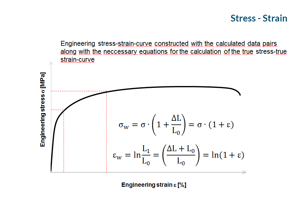
What is the difference between true stress and engineering stress?
Engineering stress is calculated using the original cross-sectional area of the component, while true stress is calculated using the instantaneous cross-sectional area. True stress is a more accurate measure of the stress experienced by the material, especially during plastic deformation, as the area changes significantly. Engineering stress is simpler to calculate but can be less accurate, especially at high strains.
When should principal stress formulas be applied in design?
Principal stress formulas are used when analyzing components subjected to multi-axial stress states. They determine the maximum and minimum normal stresses (principal stresses) and the maximum shear stress at a point, regardless of the orientation of the coordinate system. These values are critical for predicting failure under complex loading conditions. Mohr's circle is a graphical representation that helps visualize principal stresses and maximum shear stress.
Conclusion
Understanding and applying the maximum stress formula is essential for ensuring the reliability of mechanical components and systems. This article has provided a comprehensive overview of the different types of stress, relevant formulas, stress concentration factors, and common pitfalls. By accurately predicting and managing maximum stress, engineers can design safer, more durable, and more reliable products. Remember to always consider the specific loading conditions, geometry, and material properties when calculating maximum stress, and to use appropriate stress concentration factors when necessary. Furthermore, computational tools like FEA should be utilized to validate analytical calculations and analyze complex geometries.