
Cable-stayed bridges, elegant structures that combine aesthetics with engineering efficiency, rely on a network of cables to support the bridge deck. Understanding the axial stress in these cables is paramount for ensuring the bridge's structural integrity and longevity. This article delves into the axial stress formula relevant to cable-stayed bridges, exploring its derivation, applications, and considerations.
Understanding Axial Stress in Cables
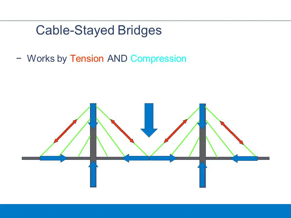
Axial stress, also known as tensile or compressive stress, arises when a force acts perpendicular to a cross-sectional area of a material. In the context of cable-stayed bridges, the primary force acting on the cables is tension, pulling along the cable's axis. Therefore, we are primarily concerned with tensile axial stress in this scenario. The fundamental formula for axial stress is:
σ = F/A
where: σ (sigma) represents the axial stress, typically measured in Pascals (Pa) or pounds per square inch (psi).
F represents the axial force acting on the cable, measured in Newtons (N) or pounds (lb).
A represents the cross-sectional area of the cable, measured in square meters (m²) or square inches (in²).
This formula reveals a direct relationship: a larger force or a smaller cross-sectional area will result in a higher axial stress.
Derivation of the Axial Stress Formula
The derivation stems from the basic definition of stress as force per unit area. Imagine a cable subjected to a tensile force, F. This force is uniformly distributed across the cable's cross-sectional area, A. The axial stress, σ, is then simply the magnitude of this force divided by the area over which it acts. This assumes that the force is applied uniformly across the cross-section, which is a reasonable approximation for cables under tension in a cable-stayed bridge.
Applying the Axial Stress Formula in Cable-Stayed Bridge Analysis
The axial stress formula is crucial for several aspects of cable-stayed bridge design and analysis:
1.Cable Selection: Engineers use the formula to determine the required cross-sectional area of the cables. Knowing the expected maximum axial force on a cable (due to traffic load, wind load, and the bridge's self-weight), they can calculate the necessary area to ensure that the axial stress remains below the allowable tensile strength of the cable material (typically high-strength steel).
2.Safety Factor Calculation: Safety factors are incorporated to account for uncertainties in load estimations, material properties, and manufacturing tolerances. The allowable stress is often calculated by dividing the material's yield strength (or ultimate tensile strength) by a safety factor. The axial stress calculated using the formula is then compared to this allowable stress to verify the design's safety.
3.Bridge Monitoring: Strain gauges are often installed on cables to monitor their elongation under load. Strain (ε) is related to stress through Young's modulus (E) by the equation σ = Eε. By measuring the strain, engineers can calculate the axial stress and verify that the cables are performing as expected. This is particularly important for detecting potential overload situations or cable degradation.
4.Fatigue Analysis: Cables are subjected to cyclical loading due to varying traffic loads and wind conditions. This can lead to fatigue failure over time. The axial stress formula is used to determine the stress range (the difference between the maximum and minimum stress) in the cables during each load cycle. This information is then used in fatigue analysis to predict the cable's lifespan and schedule maintenance accordingly.
Example 1: Calculating Axial Stress in a Cable
A cable in a cable-stayed bridge is subjected to a tensile force of 5 MN (Mega Newtons). The cable has a diameter of 150 mm. Calculate the axial stress in the cable.
Solution
1.Calculate the cross-sectional area:
A = πr² = π(d/2)² = π(0.15 m / 2)² ≈
0.0177 m²
2.Calculate the axial stress:
σ = F/A = (5 x 10^6 N) / (0.0177 m²) ≈
282.5 MPa
Therefore, the axial stress in the cable is approximately 282.5 MPa.
Example 2: Determining Required Cable Diameter
A cable in a cable-stayed bridge needs to withstand a maximum tensile force of 8 MN. The allowable tensile stress for the cable material is 400 MPa. Determine the required diameter of the cable.
Solution
1.Rearrange the axial stress formula to solve for area:
A = F/σ = (8 x 10^6 N) / (400 x 10^6 Pa) = 0.02 m²
2.Calculate the required radius:
A = πr² => r = √(A/π) = √(0.02 m² / π) ≈
0.0798 m
3.Calculate the required diameter:
d = 2r = 2 0.0798 m ≈
0.1596 m =
159.6 mm
Therefore, the required diameter of the cable is approximately 159.6 mm.
Factors Affecting Axial Stress in Cable-Stayed Bridge Cables
Several factors can influence the axial stress in the cables of a cable-stayed bridge: Live Load: The weight of vehicles and other traffic on the bridge deck directly contributes to the tensile force in the cables. Dead Load: The self-weight of the bridge deck, cables, and supporting structures also induces tensile stress. Wind Load: Wind pressure on the bridge deck and cables can create additional tensile forces, especially in extreme weather conditions. Temperature Variations: Changes in temperature can cause the cables to expand or contract, altering the axial stress. Expansion joints are incorporated to mitigate this effect, but some stress variation is inevitable. Cable Sag: The sag of the cables due to their self-weight introduces additional complexities in the stress analysis. The axial stress is not perfectly uniform along the cable's length due to the changing tension caused by the sag. Advanced analysis techniques, such as finite element analysis, are often used to account for cable sag accurately. Corrosion and Degradation: Over time, corrosion or other forms of degradation can reduce the effective cross-sectional area of the cable, increasing the axial stress under the same load. Regular inspection and maintenance are crucial to detect and address any signs of degradation.
Comparison to Other Stress Types
While axial stress is dominant in cable-stayed bridge cables, it's crucial to understand its relationship to other stress types: Normal Stress:Axial stress is a specific type of normal stress, which is stress acting perpendicular to a surface. Bending stress, which arises in beams subjected to bending moments, is another example of normal stress.
Shear Stress: Shear stress acts parallel to a surface. While shear stress is typically less significant in cables compared to axial stress, it can arise at the cable anchorages where the cable force is transferred to the supporting structure.
Torsional Stress: Torsional stress arises from twisting forces. Cables in cable-stayed bridges are generally designed to resist torsion, so torsional stress is usually negligible.
Common Pitfalls and Misconceptions
Assuming Uniform Stress Distribution: The axial stress formula assumes a uniform stress distribution across the cable's cross-section. While this is a reasonable approximation, local stress concentrations can occur at the cable anchorages or at points where the cable is damaged.
Ignoring Cable Sag: As mentioned earlier, cable sag can significantly affect the stress distribution. Neglecting cable sag can lead to inaccurate stress estimations, especially for long-span bridges.
Using Incorrect Units: Consistent units are essential for accurate calculations. Ensure that all quantities are expressed in compatible units (e.g., Pascals for stress, Newtons for force, and square meters for area).
How do you calculate the sag of a cable in a cable-stayed bridge?
The sag of a cable can be calculated using different formulas depending on the assumptions made. For a cable with uniformly distributed load (approximating its self-weight), the sag (s) at the midpoint can be approximated as s = (w L²)/(8T), where w is the weight per unit length, L is the span, and T is the tension at the lowest point. More complex catenary equations are used for higher accuracy, especially when the self-weight is the dominant load.
What are the common materials used for cables in cable-stayed bridges?
High-strength steel is the most common material. Specific types include parallel wire strands (PWS), compacted strands, and locked coil cables. These materials offer high tensile strength, durability, and resistance to corrosion. Protective coatings, such as galvanization or epoxy coatings, are often applied to further enhance corrosion resistance.
How does temperature affect the axial stress in bridge cables?
Temperature changes induce thermal expansion and contraction in the cables. An increase in temperature causes the cable to expand, which can increase the tension and therefore axial stress if the cable is restrained. Conversely, a decrease in temperature can reduce the tension. Engineers must account for these temperature-induced stress variations in their designs, often incorporating expansion joints and considering extreme temperature scenarios.
Conclusion
The axial stress formula σ = F/A is a fundamental tool for engineers designing and analyzing cable-stayed bridges. While seemingly simple, its application requires careful consideration of various factors, including live loads, dead loads, wind loads, temperature variations, and cable sag. Understanding the limitations of the formula and employing advanced analysis techniques when necessary are crucial for ensuring the safety and longevity of these iconic structures. By accurately calculating and managing axial stress, engineers can harness the strength and efficiency of cable-stayed bridges to create durable and aesthetically pleasing transportation infrastructure.