
Torsional stress is a crucial consideration in the design and analysis of mechanical components subjected to twisting forces. Understanding how to calculate and manage torsional stress is paramount to ensuring the structural integrity and longevity of shafts, axles, and other rotating elements. This article provides a comprehensive overview of the torsional stress formula, its derivation, applications, and limitations, equipping engineers and students with the knowledge needed to tackle real-world engineering challenges.
Understanding Torsional Stress
Torsional stress arises when a twisting force, or torque, is applied to an object, causing it to deform in a rotational manner. This type of stress is particularly relevant in components designed to transmit power, such as drive shafts, axles, and torsion bars. The magnitude of the torsional stress is dependent on several factors, including the applied torque, the geometry of the object, and the material properties. Unlike tensile or compressive stress which act normal to a surface, torsional stress is a shear stress acting parallel to the cross-section.
Deriving the Torsional Stress Formula
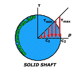
The fundamental torsional stress formula is derived based on the assumptions of linear elasticity, a homogeneous material, and a circular cross-section. Consider a solid circular shaft subjected to a torque T. The shear stress (τ) at a radial distance (r) from the center of the shaft is given by:
τ = (T r) / J
Where: τ is the shear stress (typically in Pascals or psi)
T is the applied torque (typically in Newton-meters or lb-in)
r is the radial distance from the center of the shaft to the point where stress is being calculated (typically in meters or inches)
J is the polar moment of inertia of the shaft's cross-section (typically in m4 or in4)
The polar moment of inertia (J) represents the resistance of the cross-section to torsional deformation. For a solid circular shaft with radius R, the polar moment of inertia is:
J = (π R4) / 2
For a hollow circular shaft with outer radius Ro and inner radius Ri, the polar moment of inertia is:
J = (π (Ro4 - Ri4)) / 2
The maximum shear stress occurs at the outer surface of the shaft (r = R):
τmax = (T R) / J
This formula allows engineers to determine the maximum shear stress experienced by a shaft under torsion, a critical parameter in design calculations.
Applications of the Torsional Stress Formula
The torsional stress formula finds wide application across various engineering disciplines. Several key application areas include: Shaft Design: Determining the required diameter of a shaft to withstand a given torque without exceeding the material's allowable shear stress. This is crucial in designing drive shafts for vehicles, motors, and machinery. Axle Design: Analyzing the torsional stress in axles to prevent failure due to twisting forces. This is particularly important in heavy-duty applications like trucks and construction equipment. Torsion Bar Design: Calculating the torsional stiffness and stress in torsion bars used in suspension systems. Torsion bars act as springs that resist twisting, and proper stress analysis is vital for their performance and durability. Coupling Design: Ensuring that couplings connecting shafts can transmit the required torque without failing due to torsional stress. Drill String Analysis:Evaluating the torsional stress in drill strings used in oil and gas exploration to prevent breakage and ensure efficient drilling operations.
Calculating Angle of Twist
In addition to torsional stress, the angle of twist (θ) is another important parameter to consider when analyzing torsion. The angle of twist represents the amount of rotation that occurs along the length of the shaft under torsion. The formula for the angle of twist is:
θ = (T L) / (G J)
Where: θ is the angle of twist (in radians)
T is the applied torque
L is the length of the shaft
G is the shear modulus of the material
J is the polar moment of inertia
The angle of twist is crucial for ensuring that the torsional deformation remains within acceptable limits and does not interfere with the function of the mechanical system.
Worked Examples
Example 1: Solid Shaft
A solid steel shaft with a diameter of 50 mm is subjected to a torque of 500 Nm. Calculate the maximum shear stress in the shaft.
- Calculate the radius: R = D/2 = 50 mm / 2 = 25 mm =
0.025 m
- Calculate the polar moment of inertia: J = (π R4) / 2 = (π (0.025 m)4) / 2 ≈
6.136 x 10⁻⁸ m4
- Calculate the maximum shear stress: τmax = (T R) / J = (500 Nm
0.025 m) / (6.136 x 10⁻⁸ m4) ≈
20.37 MPa
Example 2: Hollow Shaft
A hollow aluminum shaft has an outer diameter of 80 mm and an inner diameter of 60 mm. It is subjected to a torque of 1000 Nm. Calculate the maximum shear stress in the shaft.
- Calculate the outer radius: Ro = Do/2 = 80 mm / 2 = 40 mm =
0.04 m
- Calculate the inner radius: Ri = Di/2 = 60 mm / 2 = 30 mm =
0.03 m
- Calculate the polar moment of inertia: J = (π (Ro4 - Ri4)) / 2 = (π ((0.04 m)4 - (0.03 m)4)) / 2 ≈
2.199 x 10⁻⁷ m4
- Calculate the maximum shear stress: τmax = (T Ro) / J = (1000 Nm
0.04 m) / (2.199 x 10⁻⁷ m4) ≈ 182 MPa
Limitations and Considerations
While the torsional stress formula provides a valuable tool for analyzing torsional stress, it's essential to recognize its limitations: Assumptions: The formula is based on the assumptions of linear elasticity, a homogeneous material, and a circular cross-section. Deviations from these assumptions can lead to inaccuracies. For non-circular cross-sections, more complex analysis techniques, such as finite element analysis (FEA), are required. Stress Concentrations: The formula does not account for stress concentrations that can occur at sharp corners, holes, or other geometric discontinuities. These stress concentrations can significantly increase the local stress and potentially lead to failure. Material Behavior: The formula assumes that the material behaves in a linearly elastic manner. At high stress levels, the material may exhibit non-linear behavior, such as yielding or plastic deformation, which the formula does not account for. Dynamic Loading: The formula is primarily applicable to static loading conditions. Under dynamic or fluctuating loads, fatigue failure can occur, which requires more sophisticated analysis techniques to predict. Residual Stresses:The presence of residual stresses in the material, introduced during manufacturing or heat treatment, can affect the actual stress distribution and invalidate the formula's predictions.
Practical Considerations for Real-World Applications
In real-world engineering applications, engineers must consider these limitations and incorporate appropriate safety factors into their designs. Finite element analysis (FEA) can be used to analyze complex geometries and loading conditions that are beyond the scope of the simple torsional stress formula. Material testing and experimental validation are also essential to ensure that the design meets the required performance and reliability criteria.
Beyond the Basics: Advanced Topics
Torsion in Non-Circular Cross-Sections
The torsional stress formula presented earlier is strictly applicable to circular cross-sections. Non-circular cross-sections, such as square or rectangular bars, exhibit a more complex stress distribution under torsion. The shear stress is no longer uniformly distributed around the cross-section, and the maximum shear stress typically occurs at the points closest to the center of the sides.
For rectangular cross-sections with dimensionsa(longer side) andb(shorter side), the maximum shear stress (τmax) and the angle of twist (θ) can be approximated by:
τmax ≈ (T) / (α a b2)
θ ≈ (T L) / (β G a b3)
Where α and β are coefficients that depend on the ratio a/b and can be found in engineering handbooks or calculated using more advanced methods.
Combined Loading
In many engineering applications, components are subjected to combined loading, including torsion, bending, and axial loads. Analyzing the combined stress state requires the use of stress transformation techniques and failure theories. For example, the von Mises stress criterion can be used to predict yielding under combined loading conditions.
People Also Ask
How do you calculate torsional stress in a shaft with a keyway?
The presence of a keyway in a shaft introduces a stress concentration, which significantly increases the local shear stress. A stress concentration factor (Kt) must be applied to the nominal torsional stress calculated using the standard formula. The value of Kt depends on the geometry of the keyway and can be obtained from experimental data or FEA simulations. The maximum shear stress is then calculated as: τmax = Kt (T R) / J. Keyways are common sites of fatigue failure.
What is the difference between polar moment of inertia and area moment of inertia?
The polar moment of inertia (J) is a measure of a cross-section's resistance to torsion, while the area moment of inertia (I) is a measure of its resistance to bending. For a circular cross-section, J = 2I, where I is the area moment of inertia about a diameter. Both parameters are crucial in structural analysis, but they relate to different types of loading.
When should FEA be used instead of the torsional stress formula?
FEA should be used when the geometry is complex, the loading is non-uniform, stress concentrations are significant, or the material behavior is non-linear. The torsional stress formula is only accurate for simple geometries and linear elastic behavior. FEA provides a more accurate and comprehensive analysis for complex engineering problems.
Conclusion
Understanding the torsional stress formula and its limitations is essential for engineers designing and analyzing mechanical components subjected to torsion. By considering the factors discussed in this article, engineers can ensure the structural integrity and reliability of their designs. While the simple formula provides a valuable starting point, more advanced analysis techniques, such as FEA, may be necessary for complex geometries and loading conditions. Careful consideration of material properties, stress concentrations, and dynamic loading effects is crucial for preventing torsional failures and ensuring safe and efficient operation of mechanical systems.